


This article covers the replacement of engine management sensors.
Replacing the oxygen concentration sensors
A special 22 mm wrench is required to replace or remove the upstream oxygen sensor.
The operations are shown on an engine removed for clarity.
Disconnect the negative battery terminal. Raise the vehicle on a lift.
Release the locking tab of the wiring harness connector.
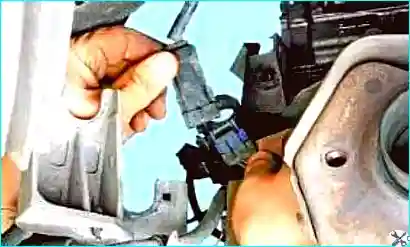
Fig. 1. Release the locking tab of the wiring harness connector
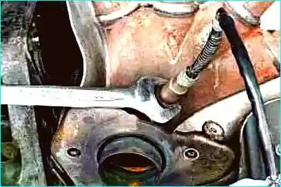
Fig. 2. Disconnect the harness connector
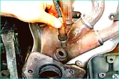
Fig. 3. Unscrew the sensor
Remove it from the exhaust manifold.
To replace the downstream oxygen sensor, carry out the following operations:
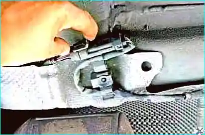
Fig. 4. Release the locking tab of the wiring harness connector
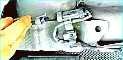
Fig. 5. Disconnect the downstream oxygen sensor connector
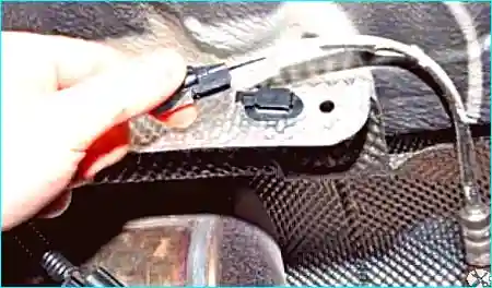
Fig. 6. Remove the wiring harness from the retainer
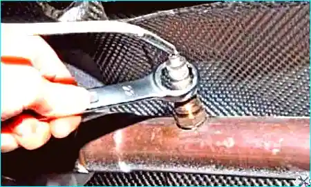
Fig. 7. Unscrew the sensor from the exhaust pipe hole
Install the sensors in the reverse order.
Tighten the lower oxygen sensor to the specified torque (45 N·m) using a 24 mm crowfoot spanner, and the upper oxygen sensor using the special tool (Mot. 1495-01).
Removing and fitting the accelerator pedal position sensor (all engines)
The position sensor forms a single assembly with the accelerator pedal. The accelerator pedal must be replaced together with the sensor.
Two types of accelerator pedal may be fitted to the vehicle: with or without an end-of-travel switch.
Vehicles fitted with a speed regulator/limiter are equipped with an accelerator pedal with a «Kick-down» end-of-travel switch.
The switch is used to cancel the speed limiting mode if the driver needs to increase speed.
It is possible to fit a pedal with an end-of-travel switch in place of a pedal without a switch.
It is forbidden to fit a pedal without a switch in place of a pedal with a switch.
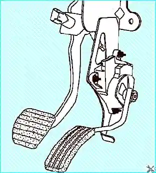
Fig. 8. Accelerator pedal
Removing and fitting the throttle control pedal
Disconnect the negative battery terminal.
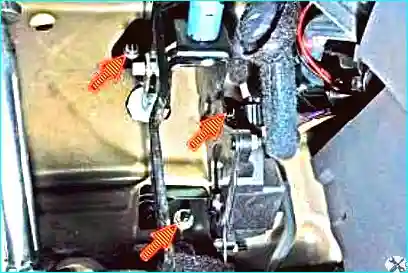
Fig. 9. Unscrew the three nuts securing the brake and accelerator pedal bracket
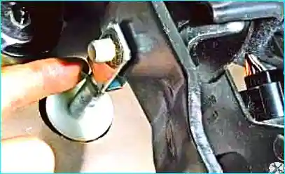
Fig. 10. Prise off the push rod pin clip of the brake servo
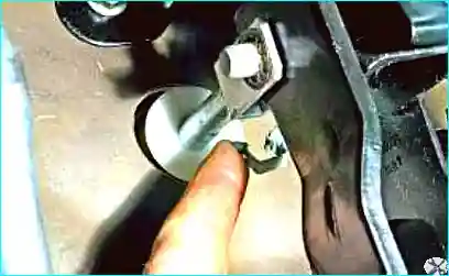
Fig. 11. Remove the clip
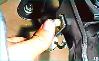
Fig. 12. Press the pin out of the holes of the brake servo push rod fork and the brake pedal
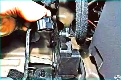
Fig. 13. Release the locking tab and disconnect the wiring harness connector from the throttle control pedal socket
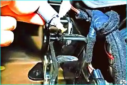
Fig. 14. Turn a quarter of a turn and remove the stop lamp switch
Remove the brake pedal complete with the throttle control pedal.
Install in the reverse order.
Crankshaft position and speed sensor (all engines)
The sensor is mounted in the upper part of the clutch housing. If the sensor fails, the engine will stop.
Before replacing the sensor, disconnect the negative battery terminal.
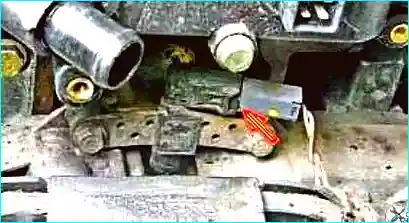
Fig. 15. Release the locking tab of the wiring harness connector and disconnect the connector from the sensor
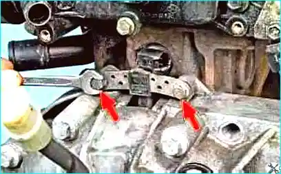
Fig. 16. Using a 10 mm spanner, unscrew the two sensor fixing bolts
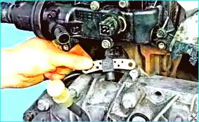
Fig. 17. Extract the sensor from the hole in the clutch housing
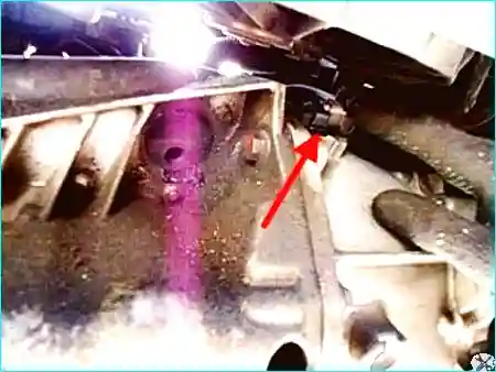
Fig. 18. Install the sensor in the reverse order
On some Renault Mégane 2 models, the crankshaft sensor is located on the side of the clutch housing (Fig. 18). It is secured with a single 6 mm bolt.
To replace or check it, remove the engine under-tray.
Disconnect the harness connector from the sensor and, using a 10 mm spanner, unscrew the sensor itself.
After replacing the crankshaft position and speed sensor or the flywheel, carry out the programming of the target area of the flywheel ring gear.
Perform two successive decelerations in 3rd gear from 4000 rpm until fuel injection resumes.
Fuel injection resumes when, during deceleration with the accelerator pedal released and fuel injection cut, the ECU again enables fuel injection.
Using a diagnostic tool, check the programming status of parameter ET089: «Programming of the flywheel ring gear target area». Read the fault codes.
If necessary, repair the fault.
Clear the fault codes from the memory. Confirm the vehicle is operating correctly.
Removing and fitting the petrol engine injection ECU (all engines)
The engine control unit is located under the bonnet, on the left-hand side of the engine, behind the battery.
Using a 10 mm spanner, disconnect the negative battery terminal.
Remove the cover from the positive battery terminal.
Using a 10 mm spanner, disconnect the positive battery terminal.
Using a T-40 spanner, unscrew the battery mounting bracket.
Move the wires aside and remove the battery.
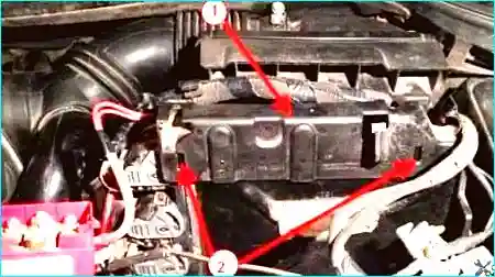
Fig. 19. Removing the ECU: 1 - plastic cover/retainer, 2 - cover locking tabs
Remove the plastic wiring retainer.
Move it slightly upwards and to the side.
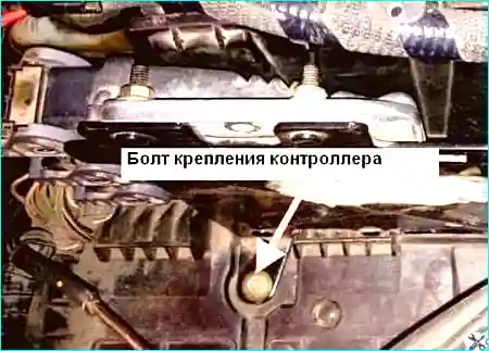
Fig. 20. Unscrew the bolt securing the ECU bracket to the battery tray
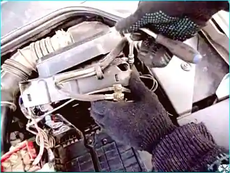
Fig. 21. Unscrew the second bracket fixing bolt
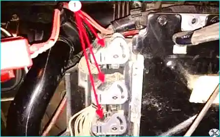
Fig. 22. Removing the ECU: 1 - ECU wiring harness connectors
Using a flat-bladed screwdriver, press the connector locking tab, lift the retainer to disconnect the connector, and pull it out. Repeat the procedure for the other two connectors.
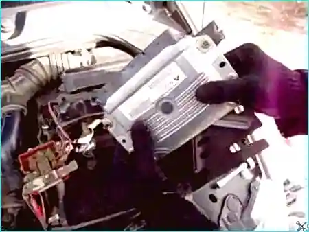
Fig. 23. Extract the ECU unit together with the bracket
Unscrew the four bolts securing the ECU to the bracket.
Install the ECU in the reverse order.
Installation
Installation is performed in the reverse order of removal.
Tighten the battery tray mounting bolts (21 N·m). Connect the leads to the battery terminals, starting with the positive terminal.
When the ignition is switched on, the throttle body must perform a programming cycle for the minimum and maximum throttle opening angles.
Removing and fitting the throttle body (K4J engine)
Removal
Disconnect the leads from the battery terminals, starting with the negative terminal.
Remove the air filter housing.
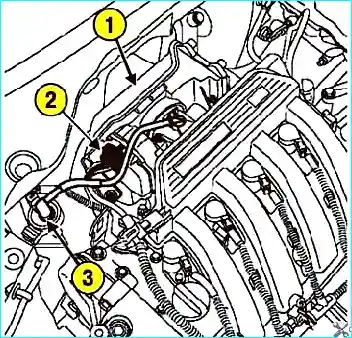
Fig. 24. Disconnecting the connector from the throttle body and the fuel vapour recovery system hose from the canister purge solenoid valve: 1 – air filter housing; 2 – wiring connector; 3 – fuel vapour recovery system hose
Disconnect the wiring connector from the throttle body and the fuel vapour recovery system hose from the canister purge solenoid valve (Fig. 24).
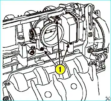
Fig. 25. Removing the throttle body: 1 – bolts
Unscrew the fixing bolts and remove the throttle body.
Installation
Installation is performed in the reverse order of removal.
The throttle body gasket must be replaced every time it is removed (use grease to aid installation).
Tighten to the specified torque:
- throttle body fixing bolt (13 N·m);
- air filter housing fixing bolts (9 N·m).
Connect the leads to the battery terminals, starting with the positive terminal.
Removing and fitting the throttle body (K4M engine)
Removal
Disconnect the leads from the battery terminals, starting with the negative terminal.
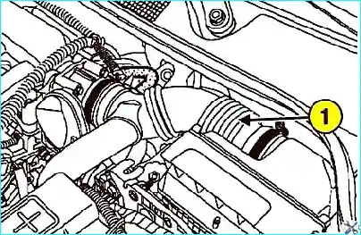
Fig. 26. Removing the air intake duct: 1 – air intake duct
Remove the air intake duct (Fig. 26).
Disconnect the wiring connector from the throttle body and the fuel vapour recovery system hose from the canister purge solenoid valve.
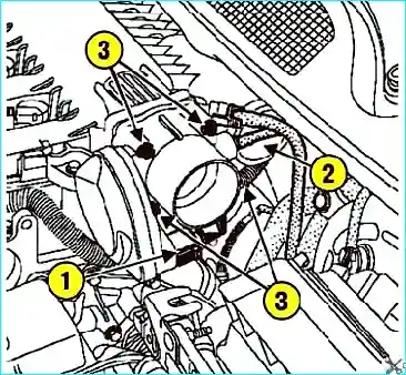
Fig. 27. Removing the throttle body: 1 – wiring connector; 2 – fuel vapour recovery system hose; 3 – fixing bolts
Unscrew the fixing bolts and remove the throttle body (Fig. 27).
Installation
Replace the gasket every time the throttle body is removed. Installation is performed in the reverse order of removal. Evenly tighten the throttle body fixing bolts to the specified torque (13 N·m).
Connect the leads to the battery terminals, starting with the positive terminal.
Removing and fitting the throttle body (F4R engine)
Disconnect the negative battery terminal.
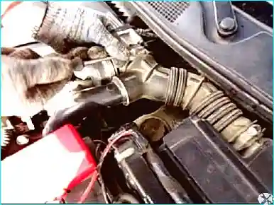
Fig. 28. Using a flat-bladed screwdriver, loosen the clamp securing the air intake duct to the throttle body
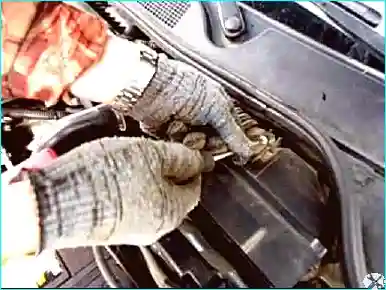
Fig. 29. Loosen the clamp securing the air intake duct to the air filter housing
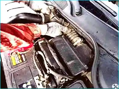
Fig. 30. Remove the air intake duct
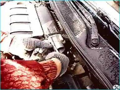
Fig. 31. Using a 10 mm spanner, unscrew the four throttle body fixing bolts
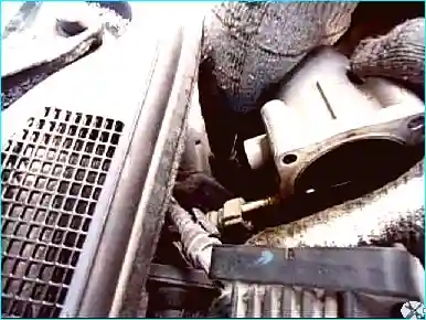
Fig. 32. Disconnect the recirculation pipe
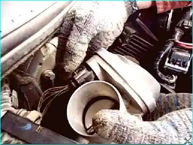
Fig. 33. Using a small screwdriver, release the locking tab and remove the throttle body control connector
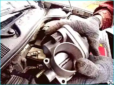
Fig. 34. Remove the throttle body for cleaning

Fig. 35. Clean the throttle body with carburettor cleaner
Blow the throttle body dry with compressed air.
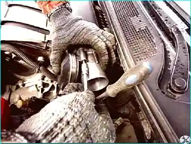
Fig. 36. Install the throttle body in the reverse order
During installation, check the rubber O-ring.
Replace the gasket every time the throttle body is removed. Installation is performed in the reverse order of removal.
Tighten the throttle body fixing bolts (F4R 776 engine) to the specified torque (10 N·m).
Evenly tighten the throttle body fixing bolts to the specified torque (13 N·m).
Connect the leads to the battery terminals, starting with the positive terminal.


