


Removing the heater core
Disconnect the leads from the battery terminals, starting with the negative terminal.
The heater assembly is shown in Figure 1.
When removing the heater core, use Figure 1 as a guide.
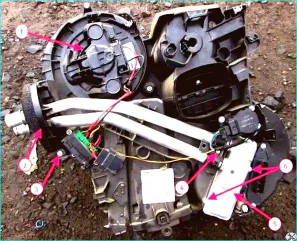
Fig. 1. Heater assembly: 1 - blower motor, 2 - pipe flange, 3 - flange retaining bolt, 4 - heater core connection clamp retaining bolt, 5 - heater core, 6 - heater core retaining screws
Pinch off the heater hoses at the bulkhead outlet in the engine compartment using suitable clamps.
Remove the access panel cover to the lower housing.
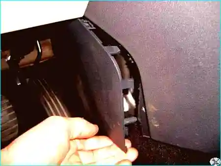
Fig. 2. Remove the dashboard side panel by releasing the spring clips
Disconnect the wiring connector from the headlamp adjuster control panel.
On vehicles with manual heating or air conditioning controls, set the temperature control to the minimum temperature position (turn the control fully to the left).
This will allow the control lever located above the heater core to be raised to its highest position.
Remove the cover.
Disconnect the air duct.
Fold the air duct downwards.
Remove the front air distribution duct.
Move aside the wiring harness secured to the dashboard crossmember reinforcement plate.
Remove the lower section of the housing that covers the dashboard crossmember reinforcement plate and partially the floor mat.
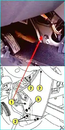
Fig. 3. Removing the dashboard crossmember reinforcement plate: 1 - reinforcement plate; 2 - retaining bolt of the flexible coupling between the unit and the reinforcement plate; 3 - retaining bolts of the reinforcement plate
Loosen the retaining bolt of the flexible coupling between the unit and the dashboard crossmember reinforcement plate (Fig. 3).
Remove the four retaining bolts from the reinforcement plate.
Remove the reinforcement plate by sliding it towards the front of the vehicle.
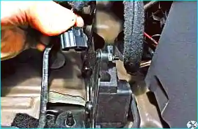
Fig. 4. Disconnecting the accelerator pedal wiring connector
Remove the wiring connector from the accelerator pedal assembly (Fig. 4).
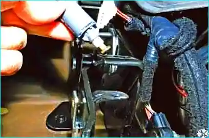
Fig. 5. Removing the stop lamp switch
Remove the stop lamp switch (Fig. 5).
Remove bolt 3 from the heater core pipe flange and withdraw flange 2 of the pipes (Fig. 1).
Unlock the flange, then lift it to remove it from the air distribution unit.
Unscrew the two heater core retaining screws 6 and the two retaining bolts 4 of the heater core connection clamps (Fig. 1).
Place a container underneath to collect any spilt coolant.
Move the heater core with its pipes aside.
Slide the clamps on the heater core pipes.
Remove the heater core pipes by pulling them towards the front of the vehicle, and remove the heater core.
Installing the heater core
When replacing the heater core, the sealing gaskets must be replaced.
Installation is carried out in the reverse order of removal.
Restore the original shape of the air duct by working through the outlet openings and straightening the bends by applying pressure perpendicular to the fold.
Tighten to the specified torque:
- reinforcement plate retaining bolts (210 N·m);
- flexible coupling retaining bolt (2 N·m).
Refill the cooling system with coolant.
Bleed the air from the engine cooling system.
Check the cooling system for leaks using tool (Ms554-07).


