


Place the vehicle on a two-post lift.
Remove the upper engine covers.
Disconnect the leads from the battery terminals, starting with the negative terminal.
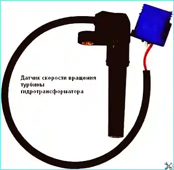
Fig. 1. Torque converter turbine speed sensor
To remove the torque converter turbine speed sensor and the vehicle speed sensor, it is not necessary to drain the oil or remove the automatic transmission.
When replacing the sensor, always remove the modular connector.
Remove the engine under-tray.
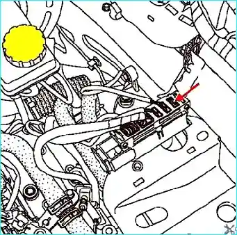
Fig. 2. Extract the connector indicated by the arrow in Figure 2 from the gearbox bracket
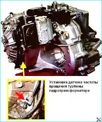
Fig. 3. Fitting the torque converter turbine speed sensor
Remove the torque converter turbine speed sensor.
Protect the connector from damage by enclosing it in a waterproof plastic bag.
Removing the vehicle speed sensor
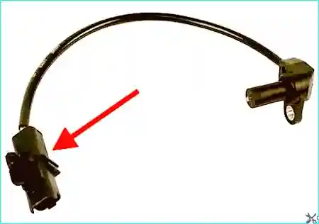
Fig. 4. Disconnect the sensor connector
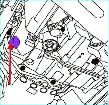
Fig. 5. Vehicle speed sensor location
Remove the vehicle speed sensor (Fig. 5).
Installation is carried out in the reverse order of removal.
Tighten to the specified torque:
- torque converter turbine speed sensor fixing bolt (10 N·m);
- vehicle speed sensor fixing bolt (44 N·m).
Replacing the wheel speed sensors
The wheel speed sensors transmit information on road speed, direction of travel, and road conditions to the hydro-electronic ABS module.
After the ignition is switched on, the control unit supplies voltage to the wheel speed sensors, which use the Hall effect.
They generate an output signal in the form of square-wave pulses, which vary in proportion to the speed of rotation of the sensor's pulse ring.
Based on this information, the control unit determines the optimum braking mode for the wheels.
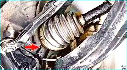
Fig. 6. The front wheel speed sensor is installed in the bores of the steering knuckles
It is removed together with the wiring harness.
To replace the front wheel sensors, place the vehicle on a lift or an inspection pit.
Disconnect the negative battery terminal.
Remove the relevant wheel.
Remove the front wheel arch liner.
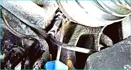
Fig. 7. Release the retaining clip
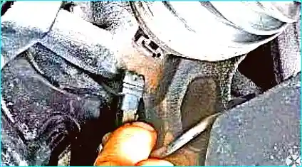
Fig. 8. Remove the sensor from the aperture in the steering knuckle
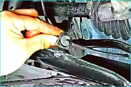
Fig. 9. Remove the harness retainer from the bracket secured to the ball joint connections
Remove the harness retainer from the front suspension arm.
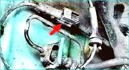
Fig. 10. Separate the connectors and remove the front wheel speed sensor complete with wiring harness
The rear wheel speed sensor is installed in the bore of the rear suspension knuckle and is removed complete with the wiring harness.
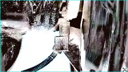
Fig. 11. To replace it, raise the rear of the vehicle and remove the relevant wheel
Release the retaining clip.
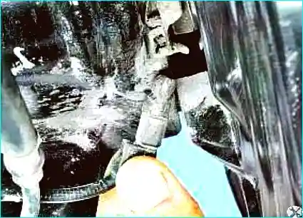
Fig. 12. Remove it from the aperture in the knuckle
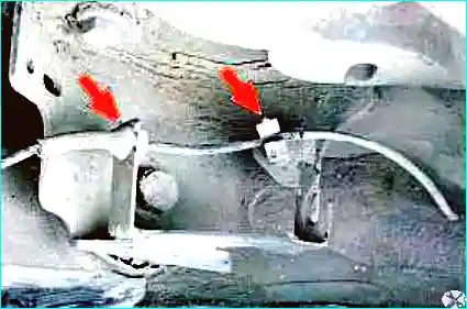
Fig. 13. Remove the wiring harness from the body bracket
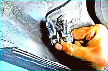
Fig. 14. Release the connector lock
Separate the harness connectors.
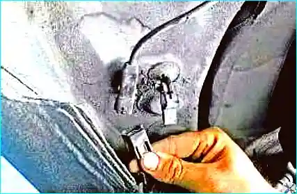
Fig. 15. Remove the rear wheel speed sensor complete with wiring harness
Install the sensors in the reverse order.
If, after replacing the wheel speed sensor, the ABS warning light does not go out when the vehicle is driven, the ABS system should be diagnosed.


