


Cylinder head removal
Place the vehicle on a two-post lift.
Disconnect the battery.
Remove the battery.
Remove the upper engine covers.
Remove the engine under-tray.
Remove the auxiliary drive belt.
Remove the timing belt.
Remove the front bumper.
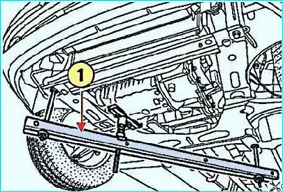
Fig. 1. Installing the engine support bar: 1 – bar
Install the engine support bar (Mot1672) (Fig. 1).
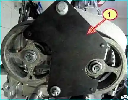
Fig. 2. Removing the camshaft timing sprockets: 1 – tool
Remove the camshaft timing sprockets after locking the shafts using the tool (Mot1490-01) (Fig. 2).
Remove the fuel rail guard and the fuel feed line to the fuel rail.
Move the fuel feed line aside.
Disconnect the vacuum hose for the brake servo from the intake manifold.
Disconnect the wiring connector from the coolant temperature sensor.
Disconnect the hoses from the thermostat housing.
Disconnect:
- the wiring connectors from the ignition coils;
- the wiring connector from the air temperature sensor;
- the wiring connectors from the absolute pressure sensor;
- the hose from the canister purge solenoid valve;
- the wiring connector from the upstream oxygen sensor.
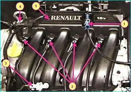
Fig. 3. Removing the intake manifold K4M engine: 1 – throttle cable, 2 – wiring harness connector to ignition coils, 3 – wiring harness connector to air temperature sensor, 4 – wiring harness connector to intake air pressure sensor, 5 – intake manifold
Disconnect the wiring connectors from the injectors.
Gather the retainers.
Move the wiring harness aside.
Remove the ignition coils and spark plugs.
Remove the air filter housing.
Remove the throttle body.
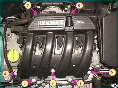
Fig. 4. Removing the intake manifold K7M engine: 1-7 – intake manifold fixing bolts
After removing the lifting eye and unscrewing the fixing bolts, remove the intake manifold (Fig. 4).
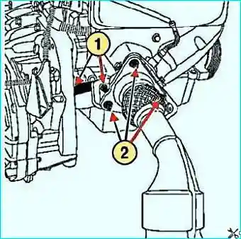
Fig. 5. Removing the exhaust pipe flange fixing: 1 – bolts; 2 – nuts
Remove the exhaust pipe flange fixing.
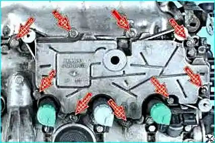
Fig. 6. Unscrew the fixing bolts and remove the oil separator
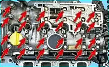
Fig. 7. Unscrew the twenty-four cylinder head cover fixing bolts
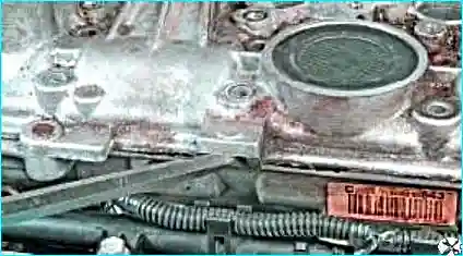
Fig. 8. Prise with a pry bar
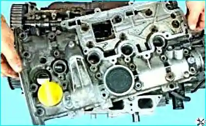
Fig. 9. Remove the cylinder head cover
Take care not to damage the mating surfaces of the aluminium alloy components.
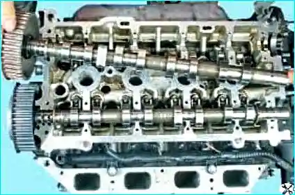
Fig. 10. Remove the exhaust camshaft
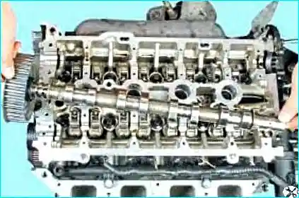
Fig. 11. Remove the intake camshaft
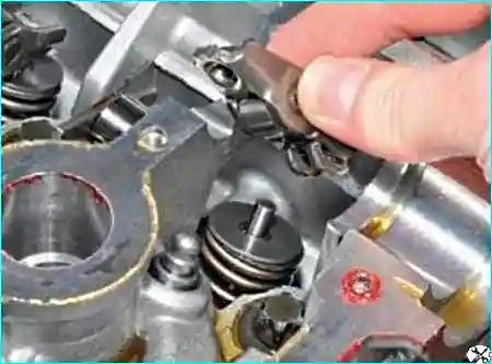
Fig. 12. Remove the rocker arms
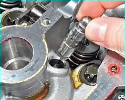
Fig. 13. Remove the hydraulic tappets
Place the hydraulic tappets upright to prevent oil leakage.
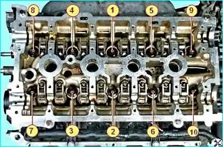
Fig. 14. Cylinder head bolt tightening sequence
Unscrew the fixing bolts and remove the cylinder head.
Mount the cylinder head on the stand (Mot1573).
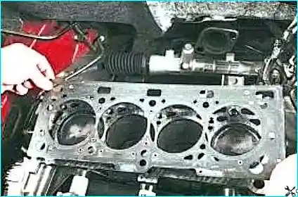
Fig. 15. Remove the gasket from the cylinder block
Cleaning the cylinder head
Clean the mating surfaces by applying Decapjoint (or equivalent) to remove gasket residue from the mating surfaces of the oil sump and the cylinder block.
After applying the compound to the surface to be cleaned, wait approximately ten minutes, then remove it with a wooden scraper.
Avoid getting the cleaning agent on the painted surfaces.
Thoroughly clean the cylinder head so that no particles enter the oil passages.
The oil feed passages may become blocked, leading to rapid engine failure.
Checking the cylinder head mating surface
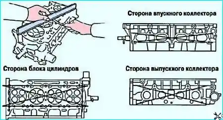
Fig. 16. Checking the cylinder head mating surface
Using a straightedge and feeler gauges, check the flatness of the cylinder head mating surface (Fig. 16).
Maximum permissible warpage: no more than 0.05 mm.
Grinding of the cylinder head is not permitted.


