


General information
Replacement of the timing belt on the Renault Megane is recommended by the manufacturer after 60 000 km of mileage.
Important! The method of replacing the timing belt is determined by the type of keyed connection at the end of the crankshaft. The connection may be with a key or without a key.
Setting the valve timing when fitting a toothed pulley without a key
Preparatory work
Precautions: to replace the belt we place the vehicle on a lift.
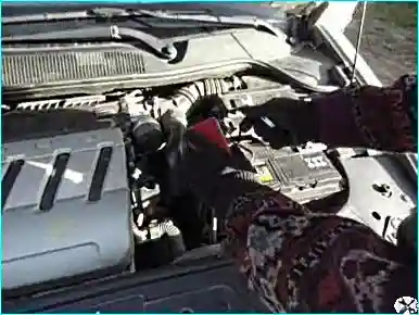
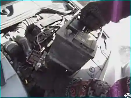
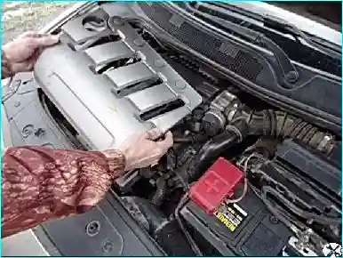
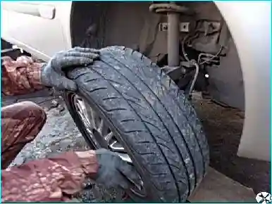
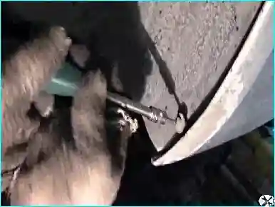
Removing the arch liner: we remove the right front arch liner. Only the front part needs to be removed. It is secured with two self-tapping screws and 5 clips.
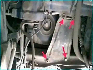
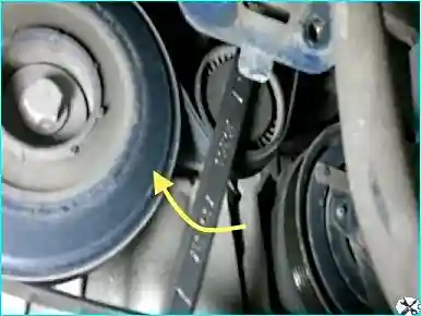
Locking the crankshaft: to unscrew the crankshaft pulley bolt, the crankshaft must be locked against turning. To do this, an assistant must engage the highest gear in the manual gearbox, press the brake pedal and apply the parking brake.
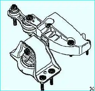
Removing the pendulum suspension mount: to withdraw the mount, the engine must be raised and lowered, otherwise the air conditioning pipe gets in the way.
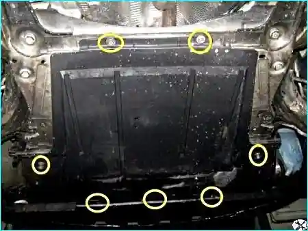
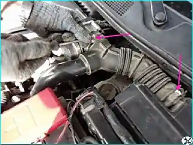
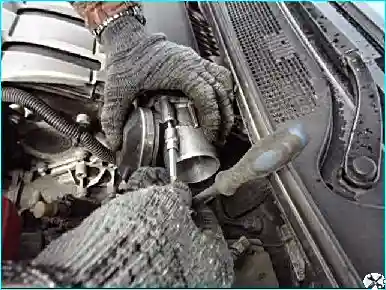
Setting TDC
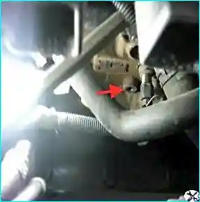
We unscrew the plug under the TDC retainer.
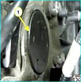
Removing the plugs: we prise up with a thin blade and withdraw the camshaft plugs. The plugs are covers of thin aluminium coated with rubber. In the middle of the plugs there are rubber discs. It is also possible to remove these plugs and, through the openings thus formed, prise up and withdraw the plugs with a flat-blade screwdriver. But in this case it will be necessary to select rubber plugs of the corresponding diameter and close these openings.
Important! In order not to disturb the valve timing, before removing the F4R timing belt it is necessary to set the crankshaft and the camshafts to the TDC position (top dead centre of the compression stroke of cylinder 1).
To turn the crankshaft we refit the bolt securing the auxiliary drive pulley, having placed a spacer (a bush or a set of washers) between the bolt and the end face. The crankshaft can also be turned by rotating the right front wheel fitted in place clockwise with the highest gear engaged in the manual gearbox. In order to make turning the shaft easier we unscrew the spark plugs.
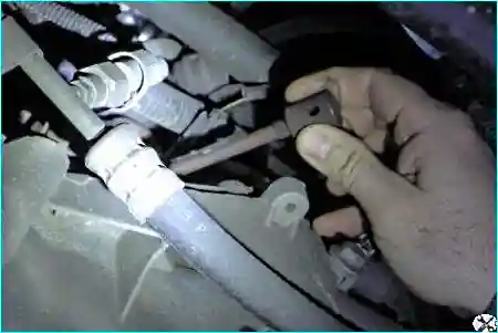
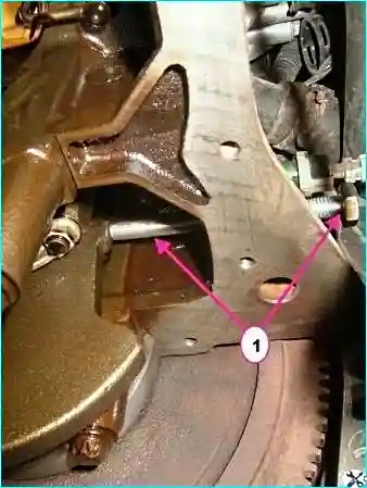
If the tool is not available: a bolt or a rod of 8 mm diameter and at least 70 mm long can be used.
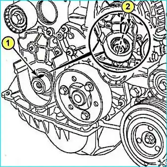
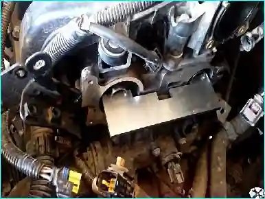
If the tool is not available: it can be made from a metal plate 5 mm thick according to the drawing.
Removing the belt
Degreasing: always degrease the end of the crankshaft on the timing drive side, the opening and the supporting surfaces of the camshaft toothed pulley, the supporting surfaces of the crankshaft pulley, the ends of the camshafts on the drive side, the openings and the mounting surfaces of the camshaft toothed pulleys.
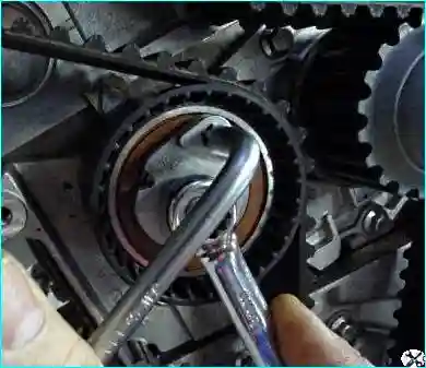
Loosening the pulleys: we loosen the camshaft securing nuts, but do not unscrew them (we leave a gap of 0.5–1 mm between the nut and the pulley). The camshaft pulleys must rotate freely on the camshafts.
Having loosened the tensioner roller, we remove the old belt.
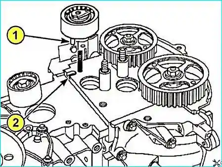
Recommendation: when replacing the auxiliary equipment drive belt within the periods established by the manufacturer, always replace the belt, the tensioner and guide rollers, as well as the damper, which consists of two parts.
We fit the new belt. First screw in the crankshaft pulley securing bolt. Do not tighten the bolt, the gap between the bolt and the pulley must be 2–3 mm.
Tensioning the belt
Before tensioning: make sure that between the nuts and the camshaft toothed pulleys the gap of 0.5–1 mm has been preserved. (The tensioner roller must not be rotated anticlockwise).
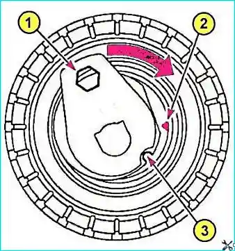
We turn the toothed pulley of the exhaust valve camshaft six revolutions in order to take up the belt clearances (the shafts remaining stationary).
We align again the marks (2) and (3) on the tensioner roller, having first loosened the axle securing nut by not more than one revolution, and finally tighten the axle securing nut of the tensioner roller to a torque of 28 N·m.
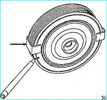
Tightening the crankshaft pulley bolt: we tighten the crankshaft pulley securing bolt to a torque of 20 N·m. (The TDC retainer must then be located in the corresponding slot of the crankshaft).
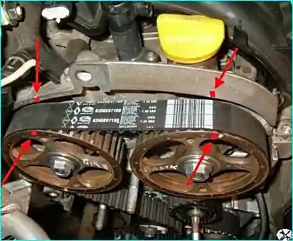
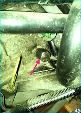
We withdraw the Mot.1054 TDC retainer. Lock the flywheel (it can be locked with a screwdriver by inserting the screwdriver into the flywheel ring gear).
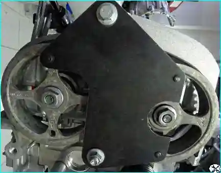
Final tightening:
- We screw in the nuts of the camshaft gears.
- After carrying out all these operations we remove all the retainers and turn the crankshaft two revolutions.
- We make sure of the correct coincidence of TDC and the position of the camshafts.
- Always replace the securing bolt and the crankshaft pulley.
- Lock the engine flywheel with a large screwdriver.
- Tighten the crankshaft pulley securing bolt to a torque of 40 N·m, then tighten further by 110° ± 10°.
Final operations
Important! In order not to damage the crankshaft pulley, do not start the engine if the auxiliary drive belt is not fitted.
Fit the auxiliary drive belt. Fit the plug of the opening under the top dead centre retainer, applying a small amount of sealant. Fit the new plugs of the inlet valve camshaft and the exhaust valve camshaft.
Fitting of the remaining components is carried out in the reverse order to removal.
Additional information: before fitting the lower plastic timing cover, make sure that it is fitted before tightening the crankshaft pulley bolt — after tightening it will be impossible to fit it.


