
Drive shafts transmit torque from the engine, gearbox, and differential to the front wheels.
The drive shafts are splined to the differential axle gears in the gearbox housing.
The splined end of the drive shaft's inner joint is secured to the axle gear by a snap ring.
During installation, the snap ring is compressed, entering the shaft groove.
Once the shaft is fully installed in the differential axle gear, the snap ring expands, preventing axial movement of the splined end.

Fig. 1. Front wheel drives: A — right front wheel drive; B — left front wheel drive; 1 — threaded section of outer joint tip; 2 — splined tip of outer joint housing; 3 — outer constant velocity joint housing; 4 — large clamp for fastening the joint boot; 5 — joint boot; 6 — small clamp for fastening the joint boot; 7 — right front wheel drive shaft; 8 — inner constant velocity joint housing; 9 — intermediate shaft support; 10 — intermediate shaft; 11 — splined tip of intermediate shaft; 12 — retaining ring; 13 — left front wheel drive shaft; 14 — threaded section of the inner joint tip
The outer joints of the drive shafts are attached to the front wheel hubs, which are mounted on bearings.

Fig. Outer constant velocity joint: 1 — boot mounting clamps; 2 — three-pin hub; 3 — roller; 4 — ABS sensor toothed disk (if equipped with ABS); 5 — joint housing; 6 — spring; 7 — adjusting spacer; 8 — pusher; 9 — drive shaft; 10 — Hinge Boot
The outer hinge consists of a housing 5 (Fig. 2) and three rollers 3 mounted on the journals of a three-spoke hub 2.
The hub is made integral with the hinge housing.
The rollers fit into the grooves of the hinge sleeve, which is made integral with the drive shaft 9.
This design allows the hinge to rotate to the required angle.
The splined tail of the outer hinge housing is secured to the front wheel hub with a nut.
The hinge is sealed by boot 10, secured with clamps 1 to the hinge housing and to the drive shaft.
For repairs of the outer hinge, only its boot and boot mounting clamps are supplied as spare parts.
In the event of a malfunction The joint must be replaced as an assembly with the drive shaft, since the joint cage and the shaft form a non-separable unit.

Fig. Right Inner Constant Velocity Joint: 1 — retaining ring; 2 — joint housing; 3 — three-pin hub roller; 4 — boot mounting clamps; 5 — Hinge boot
The right inner hinge consists of a housing 2 (Fig. 3) and three rollers 3 on needle bearings mounted on the journals of a three-pin hub.
The hinge housing contains grooves for the rollers.
The three-pin hub is secured to the drive shaft with a retaining ring 1. The rollers allow the hub to move axially in the grooves of the hinge housing, allowing the drive to be lengthened or shortened to compensate for relative movements of the suspension and the power unit.
The end of the inner hinge housing with internal splines is mounted on the splined shank of the right axle gear.
The hinge housing is secured against axial movement on the shank of the gear during suspension operation by an expansion spring installed inside Joint.
The joint is sealed by boot 5, secured with clamps 4 to the joint housing and the drive shaft.
In the gearbox housing, the end of the joint housing is sealed with a toroidal rubber ring and a self-tightening oil seal.
Two repair kits are supplied as spare parts for repairing the right inner joint: a large one, which includes all the joint components, and a small one, similar to the outer joint repair kit.

Fig. Left inner constant velocity joint: 1 - mud deflector; 2 - oil seal; 3 - bearing; 4 - boot holder; 5 - joint boot; 6 - three-pin hub roller; 7 - retaining ring; 8 — Drive shaft
The left inner joint consists of three rollers 6 (Fig. 4) on needle bearings mounted on the journals of a three-pin hub.
The left half-axle gear of the gearbox, which has a complex shape, serves as the joint housing.
Its internal grooves for the rollers are designed similarly to the grooves of housing 2 (see Fig. 3) of the right inner joint.
The three-pin hub is secured to shaft 8 (see Fig. 4) of the drive by retaining ring 7.
The rollers allow the hub to move axially in the grooves of the half-axle gear, allowing the drive to be lengthened or shortened to compensate for the relative movements of the suspension and the power unit.
The joint is sealed by a boot 5, which is rigidly secured Using holder 4 on the gearbox housing.
The drive shaft, rotating inside the boot in bearing 3, is sealed by oil seal 2, installed under the boot in a removable unit shared with the bearing.
For repairing the left inner joint, two repair kits are supplied in the spare parts section: a large one, which includes all the joint components except the axle gear, and a small one, which includes the joint boot and the bearing assembly with the oil seal.
The shaft is secured to the hub with a nut.
A tripod-type constant velocity joint (CV joint) is installed on the differential side of the drive shaft, ensuring low vibration levels.
The constant velocity joints are protected by rubber boots, which are secured with clamps and protect against water and dirt.
The boots must Inspect periodically for signs of damage, lubricant leaks, or cuts.
Damaged CV joint boots must be replaced immediately with new ones, otherwise the CV joints may be damaged.
Replacing the boot involves removing the drive shafts.
Signs of CV joint wear or damage, in addition to lubricant leaks, include clicking sounds when driving and turning, a humming sound when accelerating after coasting, or vibration at high highway speeds.
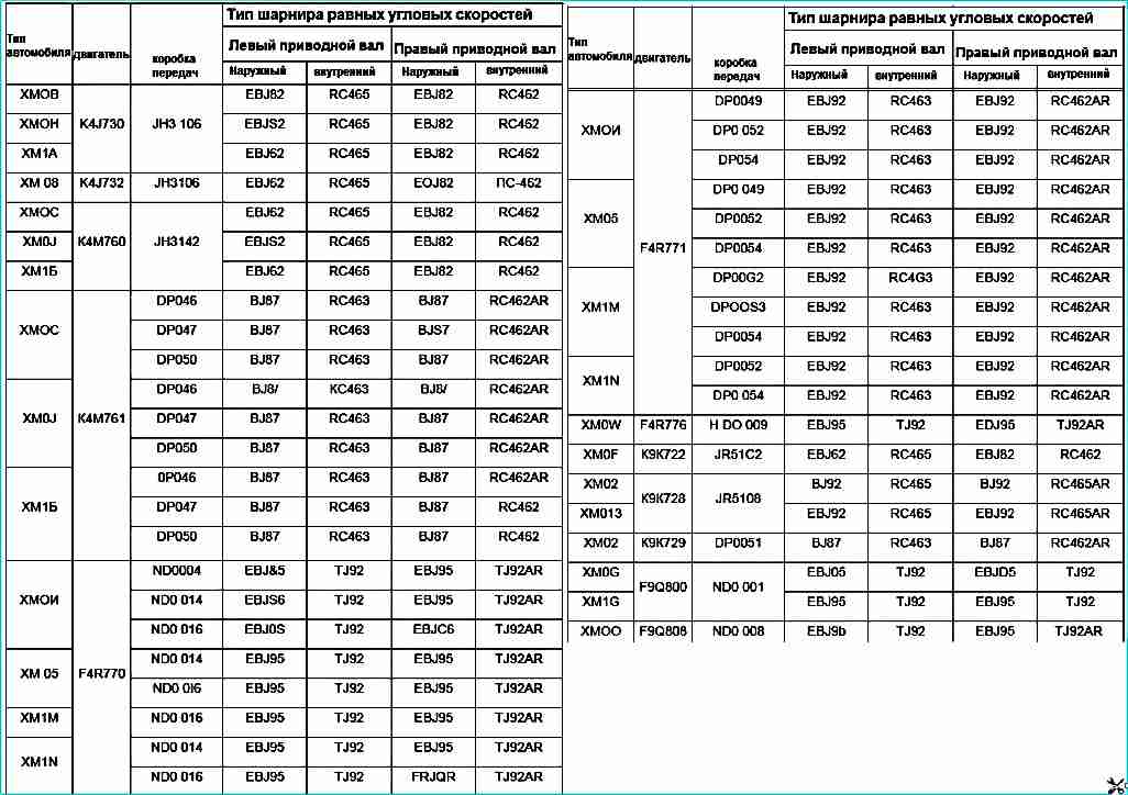
Drive shafts installed with manual transmissions jr, jh, nd, dp0

")
")
")
")
")
")
")
")