


Place the vehicle on a two-post lift.
Disconnect the battery.
Remove the engine oil pan underguard.
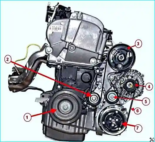
Remove the auxiliary drive belt.
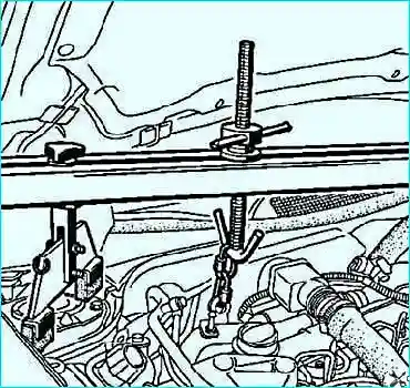
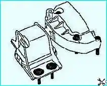
Mark the position of the pendulum suspension mount relative to the body (Fig. 2).
Remove the engine pendulum suspension mount assembly with the upper bracket.
Remove the lower thrust rod.
Be careful not to damage the air conditioning pipe.
Remove the intake silencer mounting bolts.
Remove the intake silencer.
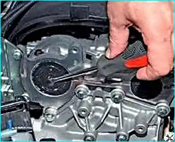
Pierce the centre of the camshaft plugs with a screwdriver.
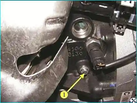
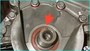
Remove the TDC pin hole plug (Fig. 4).
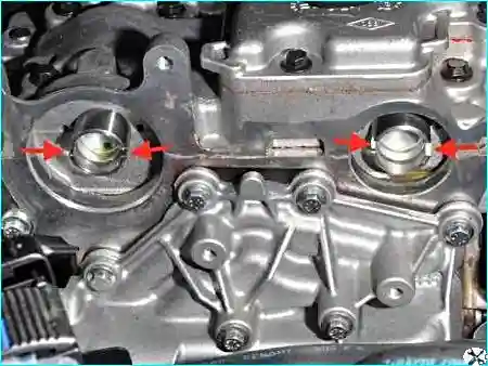
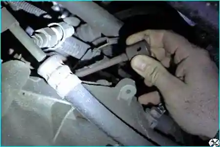
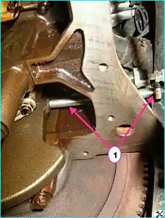
Turn the crankshaft clockwise (when viewed from the timing side) until it contacts the TDC pin (Fig. 7).
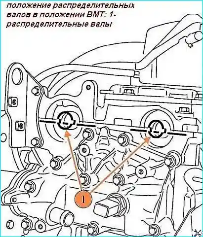
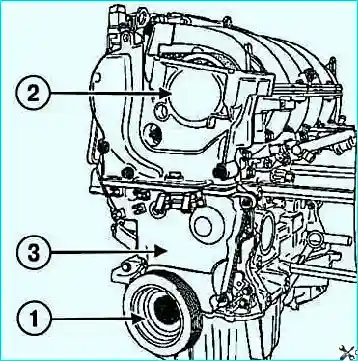
Remove the crankshaft pulley after locking the flywheel with a screwdriver, and the upper and lower timing covers (Fig. 9).
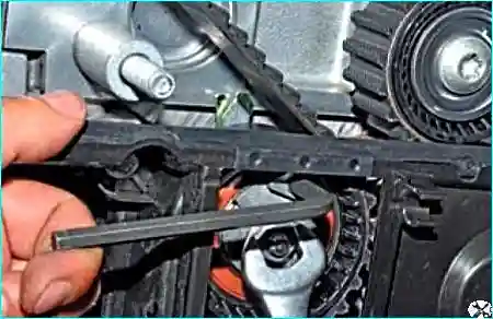
Remove the idler pulley with the special tool.
Remove the timing belt, being careful not to drop the crankshaft sprocket.
Remove the crankshaft sprocket.
Remove the tensioner.
Installation
Replace the timing belt, the crankshaft pulley bolt, the tensioner, and the idler pulley.
Degrease the end of the crankshaft (timing side), as well as the bore and contact surfaces of the pulley, the crankshaft sprocket, and the crankshaft itself.
This is necessary to prevent the timing drive from shifting; otherwise, the engine will be damaged.
Such a shift will result in engine failure.
Position the camshaft grooves horizontally and offset downwards from the camshaft axes, turning the camshafts if necessary with the special tool (Mot.799-01).
Install the tool (Mot.1750) onto the tool (Mot.1496).
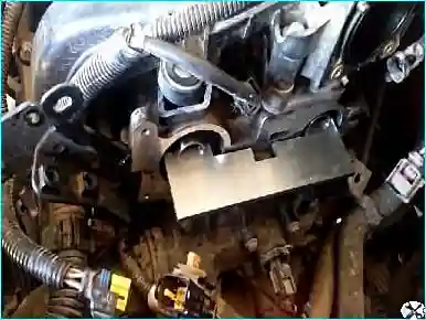
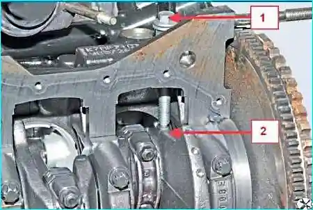
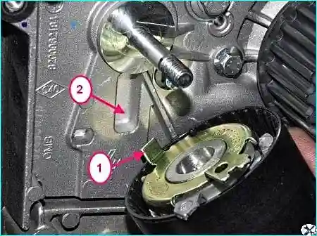
Install the crankshaft sprocket, the timing belt, and the idler pulley.
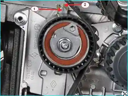
Belt tensioning
Using a 6 mm hex key, align the movable pointer with the notch by turning the eccentric clockwise.
Tighten the tensioner pivot nut to the required torque (27 N·m).
Install the pulley on the crankshaft.
Tighten the crankshaft pulley bolt to the required torque and angle (the crankshaft must be locked by the TDC pin) (40 N·m + 145° ± 15°).
Remove the camshaft locking tool (Mot.1496).
Remove the TDC pin (Mot.1489).
Turn the crankshaft two revolutions clockwise (when viewed from the timing side).
Before the end of the second revolution, screw the TDC pin (Mot.1489) into the hole in the cylinder block.
Slowly and without jerking, turn the crankshaft until it contacts the TDC pin.
Unscrew the TDC pin (Mot.1489).
Make sure the movable pointer is opposite the notch.
Loosen the tensioner fixing nut, no more than one turn, while holding the movable pointer with the 6 mm hex key.
Gently bring the movable pointer into alignment with the notch by turning the eccentric clockwise.
Tighten the tensioner pivot nut to the required torque (27 N·m).
Check
Align the movable pointer with the fixed pointer or the notch depending on the tensioner version.
Tighten the tensioner pivot nut to the required torque (27 N·m).
Before checking the valve timing, ensure the tensioner pointers are in the correct position.
Screw the TDC pin (Mot.1489) into the cylinder block hole.
Slowly and without jerking, bring the crankshaft to the stop against the pin.
Install (without force) the camshaft locking tool (Mot.1496) (the camshaft grooves must be horizontal and below the shaft axes).
If the camshaft locking tool does not fit, reset the valve timing and adjust the timing belt tension.
Remove the TDC pin.


