

Dismantling the gearbox 5DYG/5DYM26 (GAZelle NEXT)
In this article we look at dismantling the 5DYG/5DYM26 gearbox.
General view and components
The gearbox comprises the following main components:
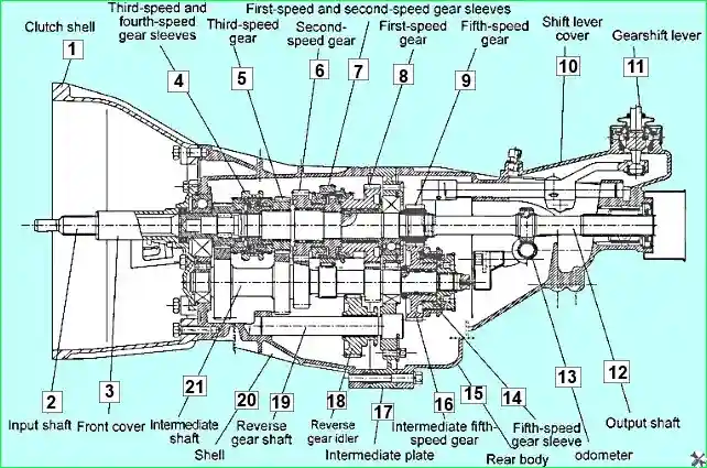
Dismantling the gearbox
Step-by-step instructions
Removal of the external components:
- remove the clutch release bearing;
- remove the clutch release fork;
- remove the clutch housing;
- remove the front cover components;
- withdraw the input shaft;
- remove the front circlip of the layshaft bearing;
- remove the control lever assembly;
- remove the gearbox cover with the gearshift mechanism;
- remove the positioning mechanism components;
- withdraw the rear housing assembly (steel ball, spring and gearshift shaft securing bolt);
- remove the gearbox shroud.
Removal of the gearshift mechanism components
- unscrew the threaded securing plug of each gearshift fork shaft;
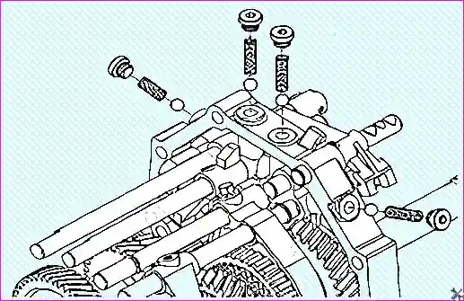
- remove the spring and steel ball;
- remove the retaining pin of each gearshift fork;
- withdraw the elastic cylindrical pin;
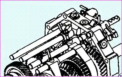
- remove the securing screws and circlip (use a drift less than 5 mm in diameter to remove the pins).
Removal of the gearshift forks
- remove the shaft of the fifth gear/reverse gear fork;
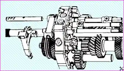
- remove the shaft of the fifth gear fork;
- remove the fifth gear fork.
Dismantling the fifth gear/reverse gear engagement mechanism
- withdraw the steel balls of the detent from the guide block;
- remove the fifth gear/reverse gear engagement guide block;
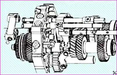
- remove the reverse gear fork shaft and the reverse gear engagement block;
- withdraw the guide rod of the reverse gear engagement lockout mechanism.
Dismantling the lockout mechanisms
- withdraw the lockout mechanism pin;
- remove the first/second gear fork shaft;
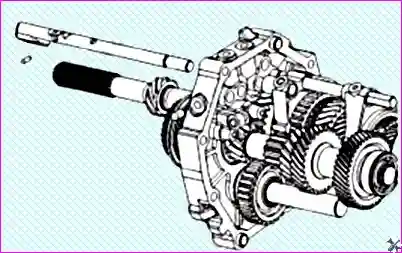
- withdraw the guide rod of the first/second gear lockout mechanism;
- repeat for the third/fourth gear fork shaft and the first/second and third/fourth gear forks.
Removal of the layshaft components
- remove the rear circlip of the layshaft;
- remove the fifth gear connecting gear;
- withdraw the fifth gear;
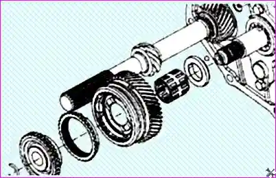
- remove the fifth gear needle bearing;
- remove the thrust washer and steel ball (6.35 mm dia.).
Dismantling the odometer and output shaft
- remove the circlip of the odometer drive gear;
- remove the odometer drive gear;
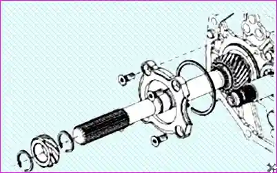
- remove the baffle of the output shaft rear bearing;
- remove the circlip of the output shaft rear bearing.
Removal of the reverse gear components
- remove the bracket of the reverse gear rocking lever;
- remove the plate of the reverse intermediate gear shaft;

- withdraw the reverse intermediate gear and the intermediate gear shaft.
Removal of the layshaft and input shaft
- remove the layshaft assembly and its bearing;
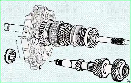
- remove the input shaft assembly and the third/fourth gear synchromesh ring (take care not to lose the input shaft needle bearing).
Removal of the output shaft
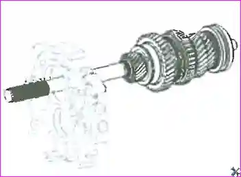
- remove the output shaft assembly.
We will look at assembling the gearbox in the next article.


