

Assembling the F4A gearbox (points 46–93)
This article describes the assembly sequence for the F4A gearbox (points 46–93), including tightening torques, tolerances and materials used.
46. Measuring the axial clearance of the reduction sun gear and selecting the thrust ring #8
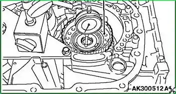
Carry out the following sequence of actions:
- fit the thinnest thrust ring #8 (thickness — 1.6 mm) onto the thrust bearing #7;
- fit the rear cover to the gearbox housing, tighten the securing bolts to 23 ± 3 N·m;
- turn the gearbox so that the converter housing fixing side is uppermost;
- fit the reduction clutch hub onto the reduction sun gear;
- measure the axial clearance of the reduction sun gear, record the result;
- permissible value: 0.25–0.45 mm;
- remove all the elements fitted in sub-points 1–4.
47. Fitting the sealing rings
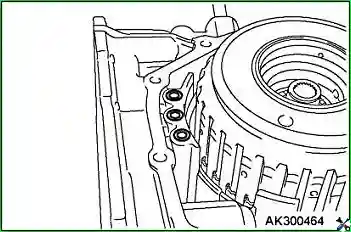
Fit three sealing rings.
48. Selecting and fitting thrust ring #8
Using the table, select thrust ring #8 whose thickness corresponds to the measured clearance (point 46.5). Fit the ring onto thrust bearing #7.
49. Applying FIPG sealant to the rear cover

Around the rear cover apply an FIPG sealant preform (forms in the working position).
Layer thickness: ~1.6 mm.
Recommended sealant: original MITSUBISHI sealant No. MD974421 or equivalent.
50. Fitting the rear cover
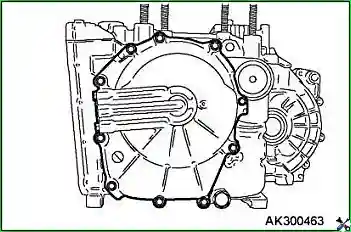
Fit the rear cover. Tighten the securing bolts to 23 ± 3 N·m.
51. Fitting the output shaft lock

Fit the output shaft lock, the adjusting ring and the spring. Then fit the lock shaft.

52. Fitting the lock support
Fit the lock support. Then fit the 2 support shafts.
53. Fitting the reduction clutch hub

Fit the reduction clutch hub.
Fit the thrust bearing with the side shown in the figure facing downwards.

54. Fitting thrust bearing #2
Fit thrust bearing #2.
55. Fitting the reduction clutch
Holding the input shaft, fit the reduction clutch.

56. Fitting thrust washer #1 (preliminary)

Fit the thinnest thrust washer #1 (thickness — 1.88 mm) onto the reduction clutch body.
Important: do not use a gasket that has already been compressed between the sealing surfaces.
57. Fitting the gasket and the working fluid pump
Using guide MD998412, fit the new working fluid pump gasket and the pump itself.

58. Tightening the working fluid pump bolts
Tighten the pump securing bolts to 29 ± 2 N·m.
59. Measuring the input shaft axial clearance and replacing thrust washer #1

Measure the input shaft axial clearance. Select thrust washer #1 whose thickness corresponds to the measured clearance. Replace the thrust washer fitted in point 56.
Permissible clearance value: 0.70–1.45 mm.
60. Fitting the working fluid filter

Fit the working fluid filter.
61. Fitting the differential

Fit the differential.
62. Placing solder wire on the differential

Place on the differential (at the points indicated in the figure) 2 pieces of solder wire: length — 10 mm, diameter — 3 mm.
63. Fitting the converter housing (preliminary)

Fit the converter housing to the gearbox housing without FIPG sealant. Tighten the securing bolts to 48 ± 6 N·m.
64. Removing the converter housing and taking out the solder wire
Unscrew the bolts, remove the converter housing. Take out the pieces of solder wire.
65. Measuring the thickness of the flattened solder wire pieces

Using a micrometer, measure the thickness of the flattened solder wire pieces.
66. Selecting the adjusting ring
Select the adjusting ring whose thickness equals the sum of the micrometer readings and the required bearing preload value.
Permissible bearing preload value: 0.045–0.165 mm.
67. Fitting the adjusting ring

Fit the adjusting ring selected in point 66.
68. Applying FIPG sealant to the converter housing

Around the converter housing apply an FIPG sealant preform (forms in the working position).
Layer thickness: ~1.6 mm.
Recommended sealant: original MITSUBISHI sealant or equivalent.
69. Fitting the sealing rings

Fit 2 sealing rings.
70. Fitting the converter housing

Fit the converter housing. Tighten the securing bolts to 48 ± 6 N·m.
71. Fitting the selector lever shaft and the output shaft lock rod

Fit the selector lever shaft and the output shaft lock rod.
72. Fitting the selector lever shaft roller
Fit the selector lever shaft roller.
73. Fitting the sealing rings on the accumulator pistons

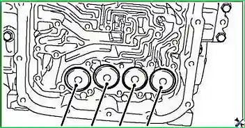
Apply new sealing rings to all the accumulator pistons. All the accumulator pistons and sealing rings are identical.
74. Fitting the accumulator springs and pistons
Identify the accumulator springs using the table:
| No. | Accumulator spring | Blue paint mark |
|---|---|---|
| 1 | Reduction and reverse gear engagement brake | Absent |
| 2 | Reduction clutch | Half of the surface |
| 3 | Auxiliary brake | Whole surface |
| 4 | Overdrive clutch | Absent |
Fit the springs and pistons into the bores of the gearbox housing.
75. Fitting the mesh filter and the oil seal

Fit the mesh filter and the oil seal of the auxiliary brake body (see figure).
76. Fitting the sealing ring into the solenoid valve cable connector
Fit a new sealing ring into the groove of the solenoid valve electrical cable connector.
77. Fitting the electrical cable connector
Insert the connector from the inside of the gearbox housing hole (see figure).
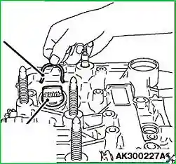
Secure the retaining ring in the groove of the electrical connector.
78. Fitting the steel balls into the hydraulic distributor

Fit one steel ball into each of the 2 upper holes of the hydraulic distributor (on the outer side).
79. Fitting the hydraulic distributor and gasket
Fit the hydraulic distributor and the gasket. Make sure the selector spool tip is in the groove of the selector lever shaft retainer.
80. Tightening the hydraulic distributor bolts

Fit the hydraulic distributor securing bolts. Tighten to 11 ± 1 N·m.
81. Fitting the temperature sensor and connecting the connector
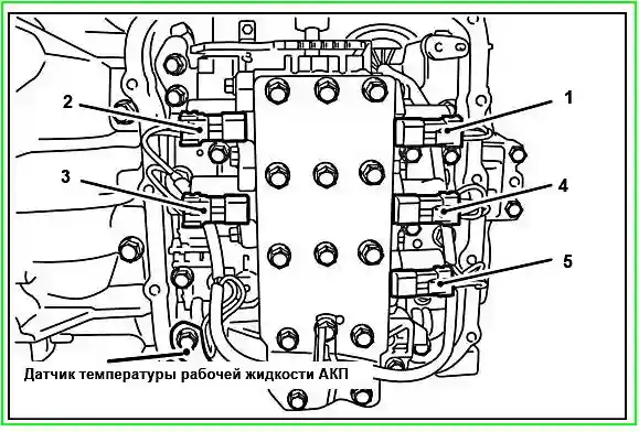
Fit the working fluid temperature sensor. Connect the electrical connector to the hydraulic distributor.
Solenoid valve correspondence table:
| No. | Solenoid valve | Wire colour | Connector colour |
|---|---|---|---|
| 1 | Reduction clutch control | White/red/red | Black |
| 2 | Overdrive clutch control | Orange/red | Black |
| 3 | Reduction and reverse gear engagement brake control | Brown/yellow | Milky white |
| 4 | Auxiliary brake control | Green/red/red | Milky white |
| 5 | Converter lock-up clutch control | Blue/yellow/yellow | Black |
82. Fitting the retainer spring and the selector lever shaft retainer

Fit the selector lever shaft retainer spring. Fit the selector lever shaft retainer.
83. Applying FIPG sealant to the distributor cover

Around the hydraulic distributor cover (see fig.) apply an FIPG sealant preform that forms in the working position.
Layer thickness: ~2.5 mm.
Recommended sealant: original MITSUBISHI sealant No. MD974421 or equivalent.
84. Fitting and tightening the distributor cover bolts

Fit the hydraulic distributor cover securing bolts. Tighten the bolts to 11 ± 1 N·m.
85. Fitting the sealing cap

Fit the sealing cap.
86. Fitting the selector switch

Fit the selector switch.
87. Fitting the selector lever
Fit the selector lever.
88. Fitting the shaft speed sensors

Fit the input and output shaft speed sensors.
89. Fitting the breather

Fit the breather so that its surface “А” is flush with surface “В” of the gearbox housing (see fig.).
90. Fitting the eye bolt
Lubricate with automatic transmission fluid (ATF) both seating surfaces of the new gasket and the threaded surface of the eye bolt. Tighten the bolt to 24 ± 3 N·m.
91. Fitting the control dipstick
Insert the control dipstick.
92. Fitting the mounting brackets
Fit the mounting brackets.
93. Fitting the converter
Before fitting, lubricate the working fluid pump hub with automatic transmission fluid (ATF). Be careful: do not damage the seal lip when fitting the converter. Fit the converter.

Check that dimension “А” (see fig.) corresponds to the installation value: 12.2 mm.
Key requirements and warnings (summary)
Replacement of consumables
- always use new gaskets, sealing rings and oil seals;
- do not reuse bolts with sealant.
Lubricants and fluids
- for lubricating/retaining elements: blue petrolatum or white petroleum jelly;
- for friction elements and rotating parts: automatic transmission fluid (ATF);
- do not apply sealant/adhesive to gaskets.
Tools
- use only the specified special tools (e.g. MD998412, MB991631, etc.);
- do not use woven gloves or rags (permitted: nylon cloth, paper towels).
Tightening torques
- strictly observe the specified tightening torques (e.g. 29 ± 2 N·m, 48 ± 6 N·m, etc.);
- use a torque wrench.
Clearance control
- check the axial clearances (e.g. 0.25–0.45 mm, 0.70–1.45 mm) and select the adjusting elements using the tables;
- record the measured values.
Sealants
- use the recommended sealants (e.g. MITSUBISHI No. MD974421);
- observe the applied FIPG layer thickness (1.6 mm, 2.5 mm, etc.).
Orientation of parts
- fit the thrust bearings with the side shown in the figure facing downwards;
- watch the position of the marks and grooves (e.g. the selector spool tip).


