
Removal
- - To avoid damaging painted surfaces, cover the front fenders with protective covers.
- - Remove the cylinder head when the coolant temperature is the same as the ambient temperature (engine cold).
- - Cap any disconnected pipes or hoses to prevent foreign particles from getting inside.
- - Be careful when disconnecting hoses; do not spill oil or other liquids.
- - Be careful when disconnecting wiring harness connectors; hold them by the connector body.
Note: When disconnecting hoses, always mark the connections first to ensure the hoses are in their original positions when reconnected.
- 1. Disconnect the cable from the negative battery terminal.
- 2. Loosen the mounting bolts and remove the decorative engine cover.

Models before 2009

Models since 2009
- 3. (Models before 2009) Remove the air filter.
- 4. (Pre-2009 models) Remove the intake air duct and air cleaner housing.
- a) Remove the mass air flow sensor.
- b) Disconnect the vent hose from the air cleaner housing.
- c) Disconnect the engine control module connector.
- d) Remove the intake air duct (B) and air cleaner housing (A).


- 5. (Models since 2009) Disconnect the ventilation hose (A), the engine control module (ECU) connector (B), and remove the air filter (C).
- 6. Remove the front wheels.

- 7. Remove the lower part of the engine guard (A).
- 8. Drain the coolant.
- 9. Remove the radiator hoses (A).

Models before 2009

Models from 2009
10. Remove the heater hoses (A).

Models before 2009

Models since 2009
11. (Pre-2009 models) Disconnect the A/C compressor switch (A), alternator connector (B), and oil pressure switch connector (C).

12. (Models since 2009) Disconnect the intake manifold variable geometry system VAV connector (A), the oil pressure switch connector (B), the knock sensor connector (C), and the air conditioning compressor switch (D).

13. (Pre-2009 models) Disconnect the CVVT valve and oil temperature sensor connectors.

14. (2009 and later models) Disconnect the CVVT valve connector (intake valves).

15. (Pre-2009 models) Disconnect the injector connectors (A).

16. (Models since 2009) Disconnect the injector connectors (A) and the ignition coil connectors (B).

17. (Pre-2009 models) Disconnect the throttle actuator (A) connector.

18. (2.4L models up to 2009) Disconnect the throttle actuator connector (A) and the manifold absolute pressure sensor connector (B).

19. (2.0L models before 2009) Disconnect the connectors for the idle speed control valve (A), throttle position sensor (B), manifold absolute pressure (MAP) sensor (C), and throttle cable (D).

20. (Pre-2009 models) Disconnect the knock sensor (B) and camshaft position sensor (A) connectors.

21. (2009 and later models) Disconnect the camshaft position sensor connector (A), fuel hose (B), brake booster vacuum hose (C), and PCV hose (D).

22. (Pre-2009 models) Disconnect the ignition coil connectors (A).

23. (Pre-2009 models) Disconnect the positive crankcase ventilation valve connector (A), coolant temperature sensor connector (B), condenser connector (C), and crankshaft position sensor connector (D).

24. (Pre-2009 models d.) Remove the fuel rail (A), brake booster vacuum hose (B), and PCV hose (C).

25. (Models since 2009) Disconnect the PCV valve connector (A), coolant temperature sensor connector (B), condenser connector (C), crankshaft position sensor connector (D), camshaft position sensor connector (E), and brake booster vacuum hose (F).

26. Remove the coolant inlet pipe.

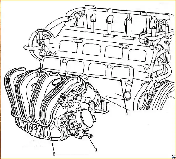
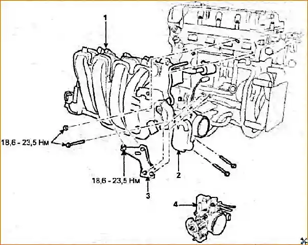
27. Remove the intake manifold.
a) Disconnect the coolant hoses (A) from the throttle body.

b) (Models before 2009) Remove the oil pressure sensor connector (A) from the bracket.

c) (Models before 2009) Remove the knock sensor connector (A) from the bracket.

d) (Models since 2009) Disconnect the sensor connectors (A) and remove the intake manifold support (B).
Tightening torque …… 19 - 24 Nm

.d) Remove the positive crankcase ventilation hose (A).

e) Remove the dipstick guide.

g) (Models before 2009) Remove the intake manifold strut (A).
Tightening torque … 19 - 27 Nm
h) (Models before 2009) Remove the intake manifold (A) together with the gasket (B).
Tightening torque … 19 - 27 Nm

i) (Models since 2009) Remove the intake manifold (A).
Tightening torque …… 19 - 23 Nm

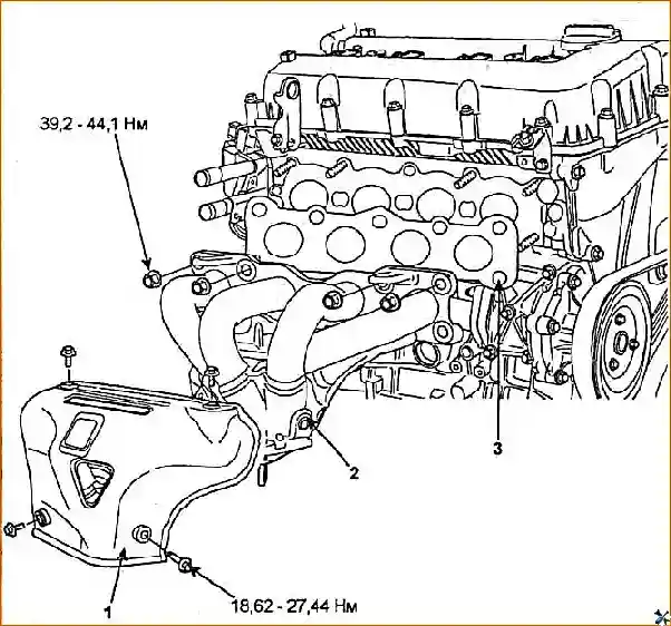
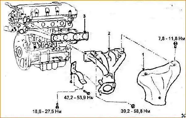
28. Remove the exhaust manifold.

- a) (Models before 2009) Disconnect the oxygen sensor connector (A).
- b) (Models before 2009) Disconnect the front exhaust pipe.
Tightening torque: 40 - 58 Nm
c) (Models since 2009) Disconnect the oxygen sensor connector (A), remove the front exhaust pipe (B), and loosen the exhaust manifold strut bolt (C).
Tightening torque:
- Nut: 40 - 58 Nm
- Bolt: 42 - 53 Nm

d) Remove the exhaust manifold heat shield (A).

Tightening torque:
- models before 2009… 19 - 27 Nm
- models since 2009… 9 - 11 Nm

d) (Models before 2009) Remove the exhaust manifold support.
Tightening torque… 52 - 57 Nm
e) Remove the exhaust manifold (A) together with the gasket (B).
Tightening torque… 40 - 44 Nm

Models before 2009

Models since 2009
- 29. Remove the timing chain (see "Timing chain Timing Belt").
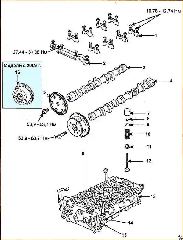
- 30. Remove the camshaft sprockets (A).

Models before 2009.

Models since 2009
- 31. Remove the camshafts (see "Checking and adjusting the valve clearances")
- 32. (Models before 2009) Remove the CVVT system valve (A) and oil temperature sensor (B).

33. (Models since 2009) Remove the CWT system valves (A).

.34. Evenly, in several passes, loosen and then unscrew the 10 cylinder head bolts in the sequence shown in the figure. Remove the washers.

Note:
- Unscrew the mounting bolts Strictly in the specified sequence. Failure to do so may result in warping or cracking of the cylinder head.
To avoid damaging the gasket surface, place the cylinder head assembly on wooden blocks after removing it from the engine.
Disassembly, Inspection, Repair, and Assembly
Checking the CVVT Actuator
- 1. Check that the CVVT actuator does not rotate.
- 2. Seal the holes on the camshaft with electrical tape, except for the one indicated by the arrow in the figure.

3. Apply compressed air to the CVVT actuator through the hole on the camshaft at a pressure of 147-150 kPa.
Caution:
- - Be careful, oil may splash when applying air.
- - If splashing occurs, remove the oil with a rag.
Note: Applying air under pressure will depress the locking pin when the actuator housing is in the position corresponding to the most recent opening and closing of the intake valves (maximum retardation angle).
4. Under the conditions specified in point "3", make sure that the housing The CVVT actuator is rotated by hand in the direction corresponding to earlier opening (and closing) of the intake valves.

- 5. Depending on the applied pressure, the CVVT actuator housing rotates without applying additional force (without turning it by hand) or, conversely, with excessive force due to the presence of air leaks, which causes the locking pin to not fully retract.
- 6. Except for the position when If the locking pin is not depressed and, accordingly, the maximum retardation angle of the intake valve opening is set, check the range of motion of the actuator. The mechanism is considered serviceable if its housing rotates back and forth without sticking from the neutral position by approximately 25°.
- 7. After completing the check, rotate the CVVT actuator housing to the position corresponding to the most recent opening and closing of the intake valves (maximum retardation angle), then stop the compressed air supply to eliminate the depressing of the locking pin.
Installation
Note:
- - Always install a new cylinder head gasket.
- - The cylinder head gasket is metal, be careful not to bend the gasket.
- - Clean all parts.
- - Install the piston of the 1st cylinder in TDC of the compression stroke.
1. Install the CVVT filter.

2. Install the new gasket (A)
Caution: Be careful not to allow gasket material or other foreign particles to enter the cylinders, cooling system passages, or lubrication system passages.

3. Install the cylinder head.
Caution: Always install new cylinder head bolts.
- a) Carefully install the cylinder head on the engine to avoid damaging the gasket.
- b) Apply a small amount of clean engine oil to the threads and under the heads of the cylinder head bolts.
- c) Install the cylinder head bolt washers with the chamfered side facing up.
- d) Gradually tighten the cylinder head bolts in three stages in the order shown in the illustration.
Tightening torque:
- Stage 1 … 34.3 Nm
- Stage 2 … 90°
- Stage 3 … 90°
Note: If the cylinder head bolt is turned a total angle of less than 180°, the bolt will not be tightened sufficiently (a secure gas joint will not be ensured).

4. Install the oil temperature sensor (B) and the CWVT system valve (A).

Caution:
Replace the solenoid valve if it has been accidentally dropped.
- - Before installing the solenoid valve, clean it.
- - To avoid damaging the solenoid valve during operations, do not hold it by the working part.
- - After installing the solenoid valve in the hole on the cylinder head, do not apply force to the valve flange.
Moments Tightening torque:
- valve …… 10 - 12 Nm
- sensor …… 19 - 24 Nm
5. Install the CVVT sprocket on the intake camshaft.

- 6. Install the camshafts (see "Checking and adjusting valve clearances").
- 7. Install Coolant inlet pipe (A).

Tightening torque:
- Bolt: 15–21 N⋅m
- Nut: 20–26 N⋅m
8. Further installation is carried out in the reverse order of removal.

")
")
")
")
")
")
")
")