
The diagram of the Cummins ISF2.8 engine management system is discussed in the article - Cummins ISF2.8 Engine Management System
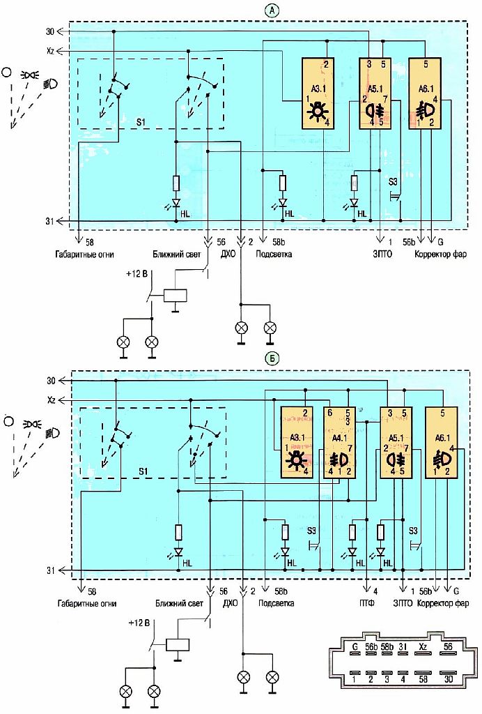
Lighting control module diagram:
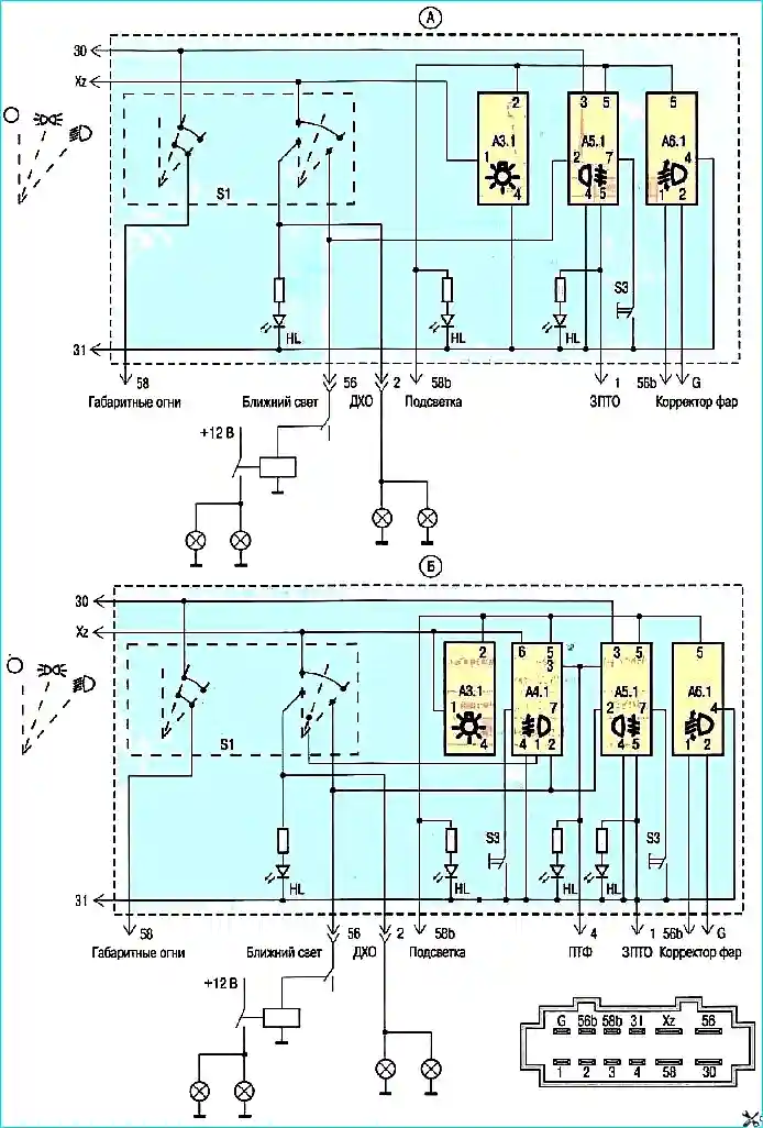
A — for lighting control module 144.3769; B — for lighting control module 145.3769; S1 — external lighting switch; S2 — fog light switch; S3 — rear fog light switch; A3.1 — symbol illumination voltage regulator; A4.1 — fog light switch electrical unit*; A5.1 — rear fog light switch electrical unit; A6.1 — Electronic headlight range control switch
* For lighting control module 1453769
Headlight diagram

Door lock control unit diagram

Left steering column switch diagram

Direction indicator and hazard warning light diagram:

E1-E4 — front and rear direction indicator lamps; E5,E6 — side direction indicator lamps; 495.3747-03 — direction indicator relay; S1 — hazard warning light switch; S2 — steering column switch
Windshield wiper and washer diagram


")
")
")
")
")
")
")
")