
Cummins ISF2.8 diesel engine, four-stroke, four-cylinder, in-line sixteen-valve, liquid-cooled, turbocharged
The engine is equipped with an electronic fuel injection system
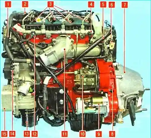
Figure 1 shows the left side of the engine.
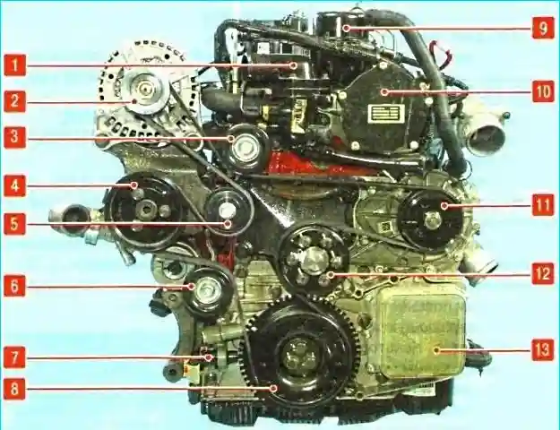
Figure 2 shows the front view of the engine.
The cylinder block is made of gray cast iron.
The cylinders are bored in the block itself.
Channels for the coolant are bored between the cylinders.

The cylinder block has bosses and holes for fastening parts and assemblies.

Five main bearing supports are made in the lower part of the cylinder block.
The main bearing caps are attached to the block with two bolts each.
The caps are machined together with the block and cannot be interchanged.
The fourth bearing cap is machined for installation of liners with flanges to limit axial movement of the crankshaft. Each cover has serial numbers stamped on it.
The oil pump is attached to the front end of the block.
The oil pump housing is made of aluminum alloy.
The front crankshaft oil seal is pressed into the oil pump housing.
The flywheel housing 8, Figure 1, is attached to the rear end of the block, to which the clutch housing is attached.
The flywheel housing is made of cast iron, and the clutch housing is made of aluminum alloy.
The cylinder head is attached to the top of the block, and a sump made of plastic is attached to the bottom.

The cylinder head is made of gray cast iron with a transverse cylinder scavenging scheme.
A metal-reinforced, shrink-resistant gasket is installed between the cylinder block and the head.
Intake and exhaust valves made of heat-resistant steel are installed in the head.
The valve stems are chromed.
The valves are equipped with one spring and are fixed through a plate with two crackers.
The springs are made of transformer steel.
The valve guides are made directly in the cylinder head and do not have bushings, therefore, when the valve guides wear out, the cylinder head is replaced.

The valves are driven by a camshaft located in the cylinder head, through rocker arms "B" with roller supports "B" and double-arm tappets "A", each of which simultaneously rests on the rods of two valves (the front rocker arm is removed in the picture).
The valve rocker arms are attached to the cylinder head bolts.
The clearances in the valve drive are adjusted using bolts with locknuts screwed into the rocker arm. The valve seats are installed in the cylinder head with tension.
There are no combustion chambers in the lower part of the head, since they are made in the bottoms pistons.
The cylinder head is covered with a plastic cover from above.

The steel five-bearing crankshaft rotates in main bearings with thin-walled steel liners with an antifriction layer.

The lower bearings "A" are bimetallic, and the upper "B" are trimetallic.
Oil drain holes are only in the upper bearings.

A hexagon for driving the oil pump is made on the front nose of the crankshaft.

A gear for driving the fuel pump and camshaft is made on the rear nose of the crankshaft.
The axial displacement of the crankshaft is fixed by the flanges of the upper shell of the fourth main bearing.

The camshaft is made of cast iron and has five bearing journals and two cam lobes per cylinder.
Groove "A" on the rear journal of the camshaft is made for installing a thrust plate in it to fix the shaft from axial movement.

At the rear end of the camshaft, a tailpiece with an internal thread is made for installing the sprocket of its drive and the timing disk of the phase sensor.

At the front end of the camshaft, a tailpiece with a diametrical groove is made for driving the vacuum pump.

The shaft rotates with the help of a single-row roller chain, which is put on the ring gear "A" of the intermediate gear "B", driven from the toothed ring gear on the crankshaft "B"

The pistons are made of aluminum alloy.
A combustion chamber is made in the piston bottoms.
To correctly install the piston in the cylinder, an arrow is applied to the upper surface.
The pistons are installed so that the arrow faces the front of the engine.
Three rings are installed on the pistons.
Two compression rings and one oil scraper ring.
The upper ring is trapezoidal.
The second compression ring has a groove.
The ring must be installed with this groove down.
The oil scraper ring consists of a cast ring and expander.
The piston is attached to the connecting rod with a floating piston pin.
The pin is held from axial movement by retaining rings in the piston bosses.

To cool the pistons, nozzles are installed on the lower part of the cylinder block, which are connected to the oil line.
Oil from the nozzles is supplied in a stream to the piston skirts.
Connecting rods steel, forged.
A tin bronze bushing is pressed into the upper head of the connecting rod.
The connecting rod cap is secured with two bolts.
The cylinder numbers are stamped on the connecting rod caps.
The connecting rod caps and the connecting rods themselves are made as a single eloe. Therefore, it is impossible to change places.
Connecting rod bearings are inserted into the lower head of the connecting rod.

The flywheel is cast iron, with a steel gear ring.
Attached to the crankshaft with eight bolts. The primary shaft support bearing of the gearbox is pressed into the central part.
The engine lubrication system is combined: the most loaded parts are lubricated under pressure, and the rest are lubricated either by directed splashing or by splashing oil flowing out of the gaps between the mating parts.
The pressure in the lubrication system is created by an oil pump installed in the front cover of the cylinder block and driven from the front end of the crankshaft.
The pump sucks oil from the engine oil pan through the oil receiver and feeds it through the oil filter into the main oil line.
Oil supply channels to the main bearings of the crankshaft branch off from the main line.
Nozzles are installed in the main bearing beds, through which oil is sprayed onto the cylinder walls and bottoms pistons.
Oil is supplied to the connecting rod bearings through channels made in the body of the crankshaft.
A channel for supplying oil to the camshaft bearings branches off from the main oil line.
Part of the oil is diverted through a hose to the turbocharger, after which it returns back to the crankcase.
Excess oil is drained from the cylinder head into the oil pan through drainage channels.
The open-type crankcase ventilation system communicates directly with the atmosphere through a valve that prevents road dust and dirt from being sucked into the engine in some operating modes when a vacuum is created in the crankcase.
The cooling system is sealed, with an expansion tank, consists of a cooling jacket made in casting and surrounding the cylinders in the block, combustion chambers and gas channels in the cylinder head.
Forced circulation of the coolant is provided by centrifugal water pump driven by a crankshaft poly V-belt that simultaneously drives the generator, power steering pump and radiator fan support pulley of the cooling system.
To maintain normal operating temperature of the coolant, a thermostat is installed in the cooling system, which closes a large circle of the system when the engine is not warmed up and the coolant temperature is low.
In addition, the radiator fan of the cooling system is equipped with a liquid-friction clutch that turns on the fan when the maximum permissible coolant temperature is reached.
Fuel system
On vehicles with GAZelle NEXT with a Cummins ISF2.8 diesel engine, a Common Rail fuel injection system is installed.
The fuel system includes the following subsystems:
- — fuel supply, which includes a fuel tank with a fuel intake, a fuel filter with a manual fuel priming pump, a fuel high pressure pump, ramp, injectors, fuel lines;
- — air supply, which consists of an air filter, turbocharger, charge air cooler, intake pipe.
The exhaust system is designed to remove exhaust gases from the engine cylinders and reduce noise levels during operation.
The power unit (engine with gearbox) is mounted on three supports with elastic rubber elements.

")
")
")
")
")
")
")
")