

The vehicle is fitted with a liquid-type heater. Heating is provided by air warmed in the heater radiator.
Outside air passes into the heater through a grille located between the windscreen and the bonnet, changes direction and is separated from rainwater. The air then flows from the air-intake box through the cabin air filter into the heater casing and, depending on the position of the mixing flaps, is directed either through the heater radiator or through the air distributors into the ducts to the nozzles on the instrument panel, the windscreen demisting and the air supply to the lower part of the cabin.
The heater only begins to work effectively once the engine coolant temperature reaches 80 °C.
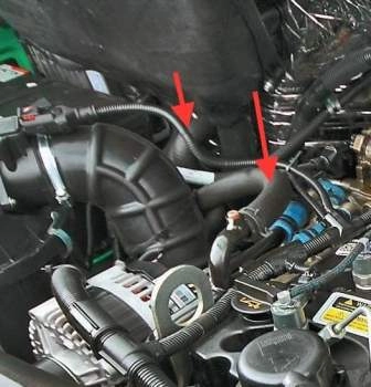
The heater radiator is connected to the engine cooling system by four hoses running in the engine compartment. The radiator is of brazed aluminium; depending on the version, EPDM or reinforced silicone hoses are used .
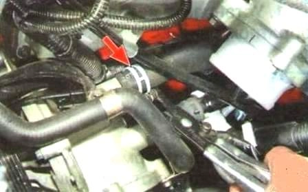
- hose connected to the heater valve;
- hose for draining fluid from the heater.
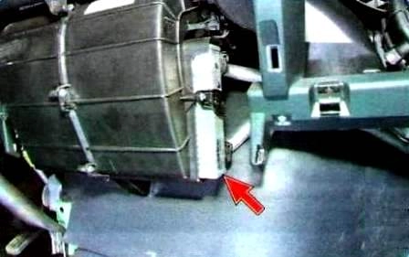
The radiator is housed in a plastic casing of the heater module mounted on the front bulkhead under the central part of the instrument panel.
Owing to the design features of the diesel engine, during prolonged idling (especially in cold weather) the coolant temperature gradually drops below normal, which among other things reduces heater efficiency.
To eliminate this drawback, an autonomous auxiliary heater is installed in the front bumper cavity on the right-hand side; it also acts as a pre-heater. It runs on diesel fuel supplied from the fuel tank by a special metering pump.
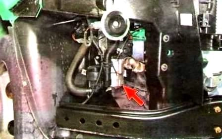
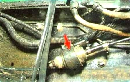
The metering pump is mounted on the inner side of the vehicle frame and connected to the fuel tank and the heater combustion chamber by special plastic fuel lines.
The auxiliary heater is switched on with the engine running and the heater on, using a switch on the instrument panel. It then operates automatically and raises the temperature of the fluid passing through the heater radiator to 80–85 °C .
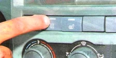
It is recommended to switch the auxiliary heater on when the outside air temperature is below 5 °C.
In pre-heater mode, the start time and operating duration are set on the timer located on the instrument panel.
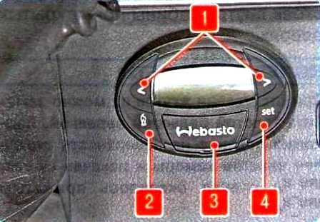
To switch on the pre-heater, press button 3. To switch on the autonomous heater in timer mode, press button 2. To select the heater operating mode, use mode-selection button 4 and buttons 1.
Replacing the cabin air filter
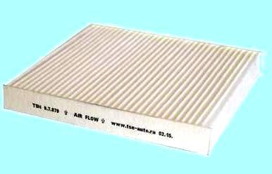
The cabin filter is replaced every 15,000 km. In dusty areas the filter should be replaced more often; the schedule also allows a check every 5,000 km and replacement every 8,000 km under severe conditions . Paper and activated-carbon filter elements are used; carbon filters additionally adsorb harmful gases .
Open the bonnet. Undo the four bolts securing the air-intake box.
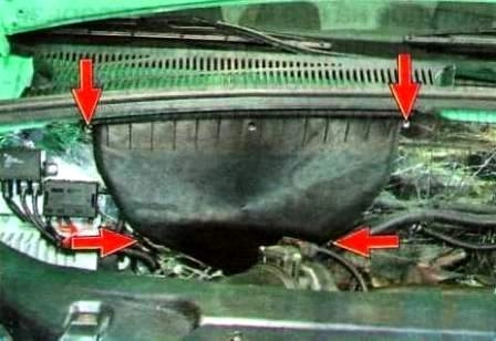
Remove the box.
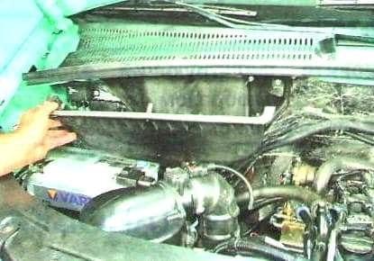
Undo the four bolts securing the filter cover and remove the cover.
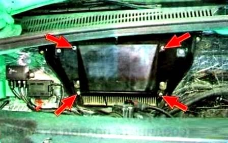
Remove the cassette with the filter element.
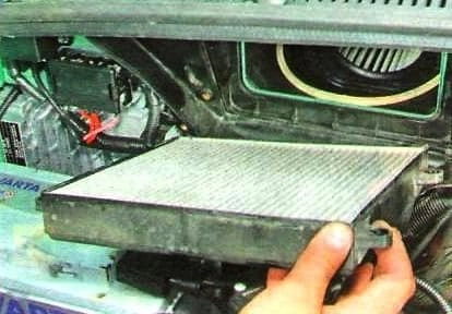
Remove the filter element from the cassette.
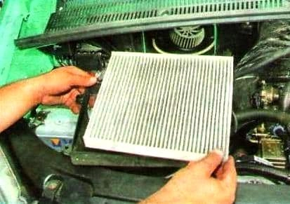
Fit a new filter element. The pleats must be vertical; when fitting the filter body onto the rear air-intake box, apply sealant adhesive along the contour without gaps .
Remove dust from the air intake with a vacuum cleaner and a damp cloth, then refit all parts.


