We are replacing the camshaft due to wear of the journals and cams of the camshaft. If the camshaft journals are heavily worn, there will be low pressure in the engine lubrication system.
Increased wear of the camshaft cams will cause valve knocking, which can no longer be eliminated by adjusting the valves.
If the camshaft seats are heavily worn, then the entire cylinder head is replaced, since they are made directly in the head body.
Prepare the car for work.
Put the car on a lift.
Disconnect the negative terminal of the battery.
Remove the engine, since there is no access to the camshaft sprocket, due to the layout on the GAZelle Next vehicle.
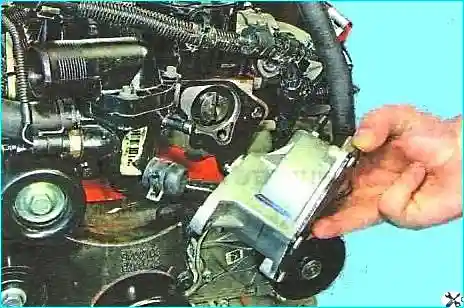
Removing the vacuum pump
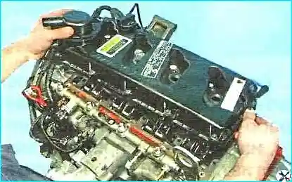
Removing the cylinder head cover (article – Replacing the cylinder head cover gasket).
Setting the TDC of the first cylinder in the compression stroke (article - Setting the TDC of the first cylinder).
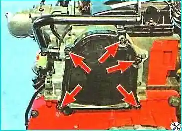
Unscrew the five bolts securing the timing case cover and remove the cover
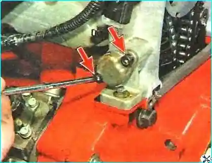
Unscrew the two bolts securing the chain tensioner cover
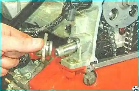
Remove the cover and extract the plunger
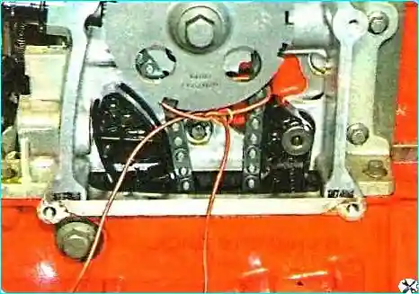
Fix the chain by tying it with wire
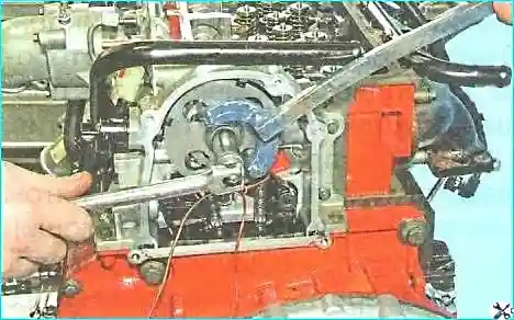
Loosen the tightening of the bolt securing the timing disk and camshaft sprocket
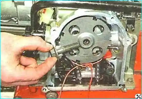
Fully unscrew the bolt securing the phase sensor disk and the camshaft sprocket
After unscrewing the bolt securing the timing disk, do not turn the crankshaft!
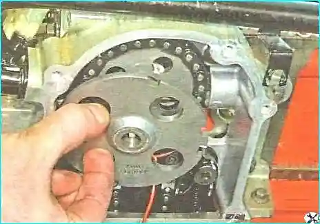
Remove the timing disk
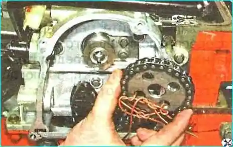
Removing the sprocket and chain from the camshaft tailpiece
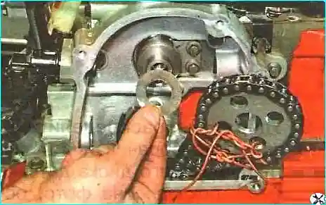
Removing the spacer washer
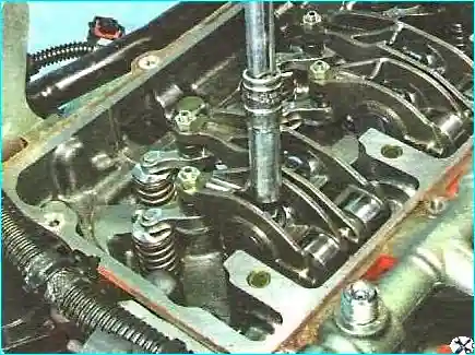
Unscrew the rocker shaft mounting bolts
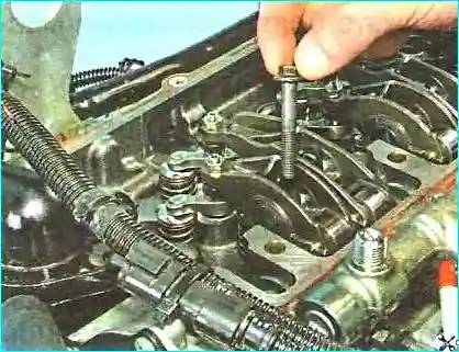
Removing the bolts from the rocker shafts
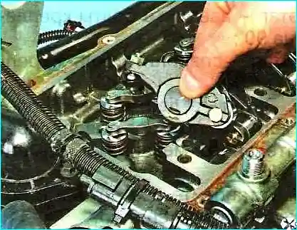
Removing the rocker arms
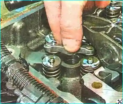
Removing the valve tappets
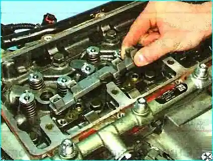
Removing the axle supports rocker arms
Mark all the parts
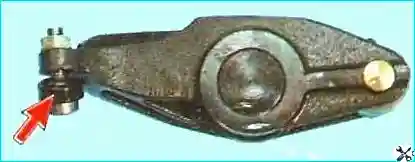
Do not remove the tip from the adjusting bolt. If it is damaged, then you need to replace the rocker arm.
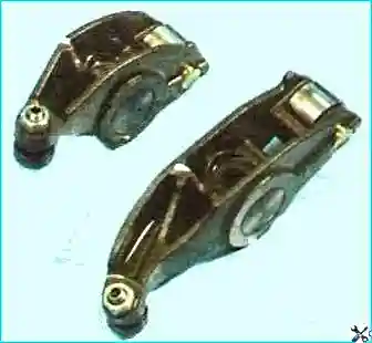
Inspect the rocker arms valves
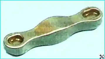
Inspect the tappets
There should be no cracks or signs of wear in the rocker arm holes for the axles.
The hole diameter should be no more than 21.014 mm.
The rocker arm roller should rotate freely on the axle and have no dents on the working surface.
Check the tappets for cracks or signs of wear.
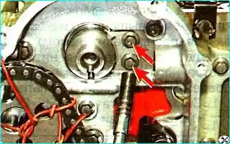
Unscrew the two bolts securing the camshaft locking plate
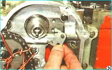
Removing the plate
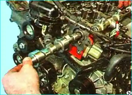
We take out the camshaft carefully, trying not to damage the working surfaces of the bearings

We inspect the camshaft
The surfaces of the bearing journals "B" and cams "A", Figure 23, should be well polished and without damage, and in the groove "B" under the locking plate there should be no traces of excessive wear and nicks.
There should be no nicks or dents on the working surfaces of the journals "B". Scoring, nicks, scratches, aluminum drag from the bearing seats in the cylinder head are allowed.
If traces of seizure, overheating, deep scratches or wear in the form of faceting, as well as uniform wear over 0.5 mm are found on the working surfaces of cams "A", replace the shaft.
Grinding of the camshaft cams is not allowed.
Measure the height of the cams.
The minimum permissible height of the intake cams is 34.51 mm, exhaust - 33.41 mm. If the values are lower, replace the camshaft.
Measure the diameters of the bearing journals.
The minimum permissible diameter of the 1st - 4th journals is 42.955 mm, 5th journal - 38.955 mm. If the values are lower, replace shaft.
The radial runout of the camshaft should be no more than 0.02 mm.
When installing a new camshaft, we recommend replacing the valve rocker arms with new ones, and before the first start of the engine and to improve the running-in conditions, add an anti-seize anti-friction additive to the engine oil.
After installing the camshaft, check its axial clearance. If it is more than 0.15 mm, replace the lock plate.
Install the camshaft in the cylinder head and all removed parts in the reverse order of removal.
Adjust the clearances in the valve drive (article - Adjusting the thermal clearances valves).
Install the engine on the car.


