
The engine is controlled by an electronic system. This includes the engine control unit ECU, which receives information from sensors.
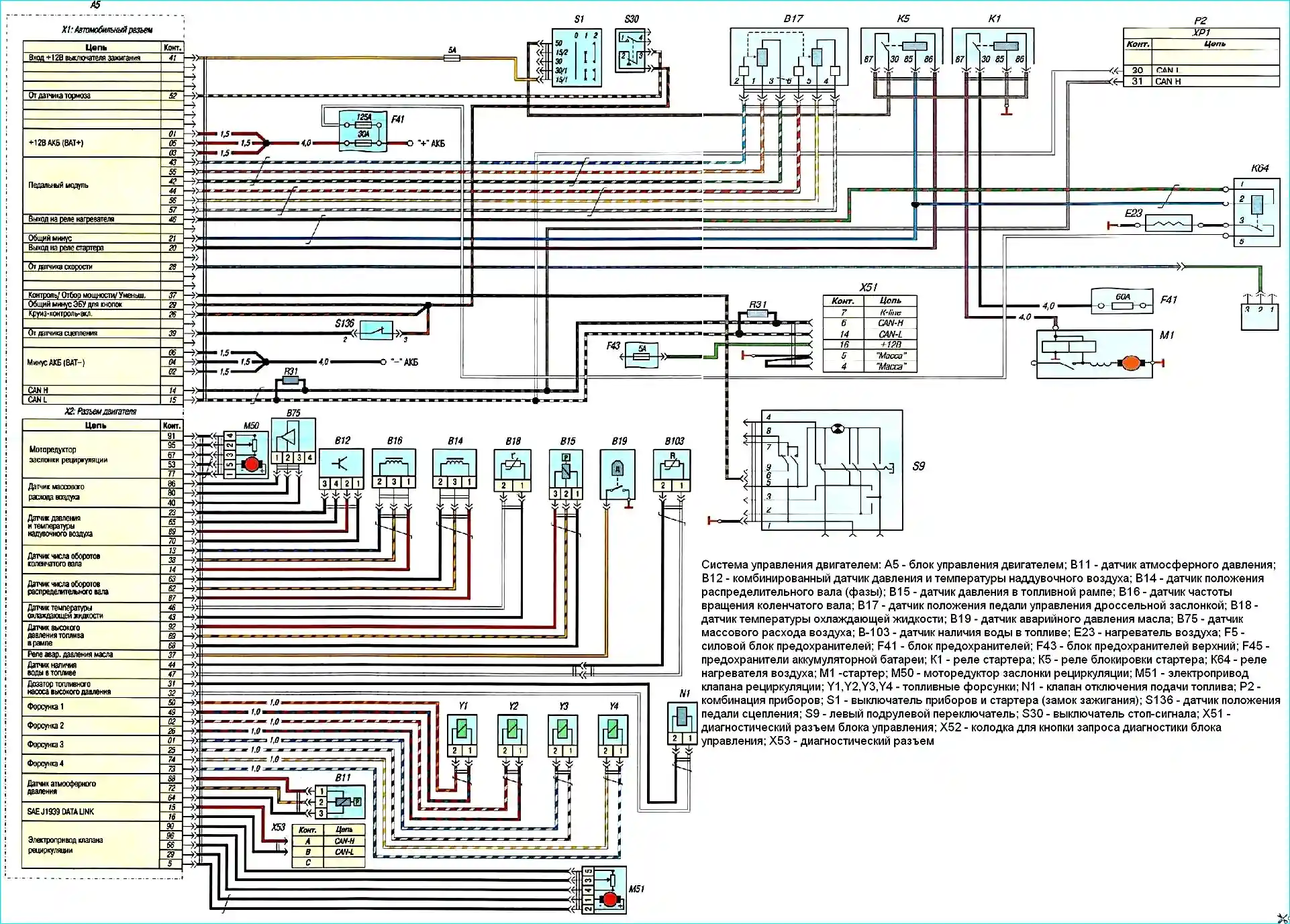
The engine control system diagram is shown in Figure 1.
- 1. Electronic engine control unit

To control the engine and a number of vehicle functions, the ECU module has two connectors: 58-pin connector of the complete equipment wiring harness and 96-pin connector of the engine wiring harness.
- 2. Crankshaft position sensor

The crankshaft position sensor is installed on the front cover of the cylinder block and is designed to synchronize the ECU with the TDC of the piston of the 1st cylinder and the angular position of the crankshaft.
When the crankshaft rotates, the teeth of the timing disk on the crankshaft change the magnetic field of the sensor, inducing AC voltage pulses.
The electronic unit determines the crankshaft speed using the sensor signals.
A sensor malfunction causes a complete failure of the engine management system: without a signal, the engine cannot be started.
- 3. Camshaft position sensor
The camshaft position sensor is the same as the crankshaft position sensor.
When the camshaft rotates, the projections of its timing disk change the magnetic field of the sensor, inducing AC voltage pulses.
The signals from the sensor are used by the ECU to organize phased fuel injection in accordance with the firing order of the cylinders.

- 4. Boost pressure sensor and air temperature sensor
The boost pressure sensor and the air temperature sensor at the inlet to the cylinders are combined into one unit (combined sensor), which is installed on the intake manifold.
Air boost is monitored and regulated using the sensor signals.
The ECU compares the measured pressure value with the values of the multi-parameter characteristic stored in its memory.
If the actual pressure value differs from the set value, the ECU regulates the boost by driving the turbine guide vane.
If the sensor is faulty, the control unit limits the boost pressure, as a result of which engine power may decrease.

The atmospheric pressure sensor is connected to the engine wiring harness block.
The atmospheric pressure data is used by the engine control unit to determine the required cyclic fuel supply during starting, as well as to adjust the fuel supply when the engine is running in areas with different atmospheric pressure.
- 5. Fuel pressure sensor

The fuel pressure sensor is installed on the fuel rail.
Based on the sensor signals, the electronic control unit controls the bypass valve of the high-pressure fuel pump, maintaining a constant pressure in the rail.
- 6. Coolant temperature sensor

The coolant temperature sensor is installed in the thermostat housing.
The electronic control unit calculates the coolant temperature based on the voltage drop across the sensor.
- 7. Accelerator pedal position sensor

The accelerator pedal position sensor is located in a single housing on the pedal assembly.
Based on the signals coming from the accelerator pedal position sensor, the ECU determines the position of the pedal.
The signal from this sensor is the main one for calculating the dose of injected fuel va.
If the accelerator pedal position sensor is faulty, the engine runs at an increased idle speed.
- 8. Clutch pedal limit switch

The clutch pedal limit switch is installed on the pedal assembly.
Its signal determines whether the clutch is disengaged or not.
When the clutch is disengaged, the cyclic dose of injected fuel is briefly reduced and the likelihood of jerking when shifting gears decreases.
If there is no signal from the clutch pedal sensor, jerking may occur when shifting gears.
In this case, the speed control system and the active vibration suppression system in the transmission do not work
- 9. Brake light switch

Brake light switch. When braking begins, the cruise control system is switched off.
If the "Accelerator pedal pressed" signal is received first, and then the "Brake pedal pressed" signal, the engine is switched to idle mode with increased rotation speed.
In the absence of a signal from the sensor, the cyclic dose of injected fuel is reduced, and the engine power is correspondingly reduced.
The injector valves are installed in the injector bodies and are electromagnetic valves controlled by the ECU.
Without a control signal, the valve ball is pressed against the seat and disconnects the high-pressure cavity of the injector and the drain line.
Under the action of the spring force and the force from the fuel pressure acting on the upper end of the injector control plunger, the injector needle is pressed against the nozzle opening and shuts off the fuel supply to the cylinder.
When when a control signal is applied, the electromagnetic valve opens, opening the communication of the cavity above the control plunger with the drain line.
At the same time, the pressure in the cavity above the plunger drops, and under the action of high fuel pressure on the lower part of the plunger, it rises together with the injector needle.
The hole in the sprayer opens - the injection process begins.
The dose of injected fuel is determined by the valve on time.

- 10. Air heating system in the intake manifold.
To facilitate engine starting at low ambient temperatures, an electric heater is built into the intake manifold.
When the key in the instrument and starter switch (ignition switch) is turned to position "1" (on), the heating element "A" of the heater in the intake manifold is turned on for a certain time depending on the air temperature.
When the heater is turned on, a signal lamp lights up in the instrument cluster.
The starter should be turned on after the signal lamp goes out.

The air intake manifold heater control unit is installed in the engine compartment on the right side.

")
")
")
")
")
")
")
")