 ZH
 FR
 BE
 DE
 RU
 UK
 KK
 EN
 ES
Removing and fitting the engine flywheel Cummins ISF2.8 (GAZelle NEXT)
We remove the flywheel during a major engine overhaul or when repairing the flywheel itself.
Tools and materials required
To carry out the work you will need: an 18 mm socket, 10, 12 and 17 mm spanners, a clutch driven plate centring mandrel, a flat-blade screwdriver, a torque wrench and a hook for extracting the flywheel.
Materials and parts used:
- New flywheel securing bolts (replacement with new ones is mandatory).
- Two M12×1,25×90 studs — to retain the flywheel during removal.
- New gearbox input shaft pilot bearing — in case of excessive play or seizing of the rolling elements.
- New flywheel — in case of severe wear of the ring gear, deep scores or scuffing on the clutch driven plate mating surface.
- Engine oil (for lubricating the parts during assembly).
- Rags, cleaner for removing contamination from the flywheel surface.
Important: after marking the flywheel position relative to the housing, the crankshaft must not be turned so as not to disturb the flywheel position. The flywheel securing bolts are evenly spaced around the circumference, so the flywheel can be fitted in one of two diametrically opposite positions determined by the dowel pins.
Preparation and removal of the flywheel
We prepare the vehicle for the work. We place the vehicle on a lift or inspection pit. We remove the gearbox. We remove the clutch.
We mark the flywheel position relative to the housing so as to refit it in its previous position (after this the crankshaft must not be turned so as not to disturb the flywheel position).
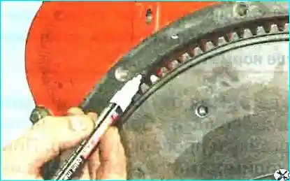
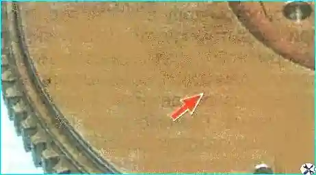
On the flywheel hub, between two adjacent securing bolt holes, a QR code mark is applied.
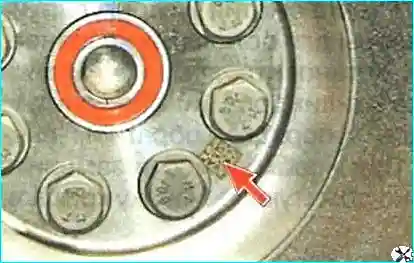
The same mark is applied to the crankshaft nose and becomes visible after the flywheel is removed.
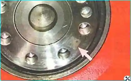
When fitting the flywheel, the same angular position of both marks must be achieved. If the marks are hard to see or missing, your own marks applied by yourself must be used.
We unscrew any two diametrically opposite flywheel securing bolts, holding the flywheel with a screwdriver to prevent it turning.
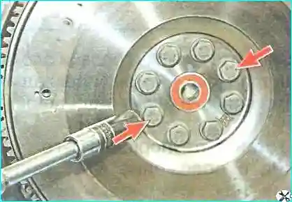
Instead of the bolts we screw in two M12×1,25×90 studs. These studs prevent the flywheel from falling when it is drawn out of the housing.
We unscrew the remaining six flywheel securing bolts.
We insert a hook into the gap between the flywheel and the housing.
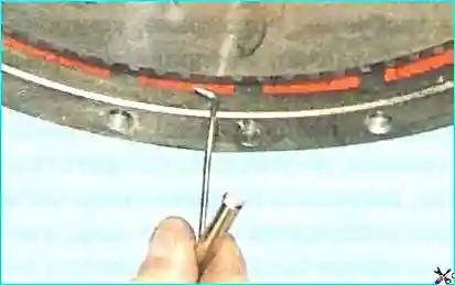
We pull the hook towards us and slide the flywheel along the installed studs.
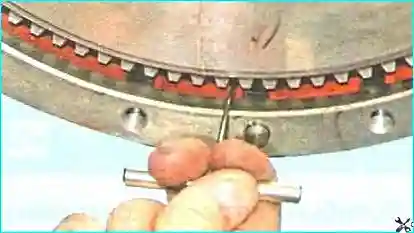
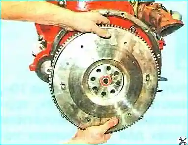
We remove the flywheel.
Inspection and repair of the flywheel
We check the condition of the ring gear; in case of severe tooth wear the flywheel must be replaced.
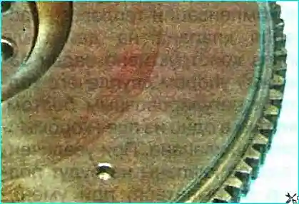
We also replace or repair the flywheel if scores or scuffing have appeared on the clutch driven plate mating surface.
The flywheel runout, measured at the ring gear, must not exceed 0.5 mm.
To remove deep scores and scuffing, the clutch driven plate mating surface may be ground, but the layer of metal removed must not exceed 0.3 mm.
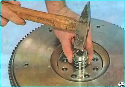
We check the condition of the gearbox input shaft pilot bearing pressed into the flywheel recess. In case of excessive play or seizing of the rolling elements, the bearing must be replaced.
We press in the new bearing, applying force to the bearing outer ring with a suitable mandrel.
Fitting the flywheel
We refit the flywheel according to the marks in the reverse order. The flywheel bolts must be replaced with new ones.
Flywheel bolt tightening sequence:
- first tighten to 30 N·m;
- undo by 180°;
- tighten to 30 N·m;
- turn once by 90°.