


Main faults of the final drive:
- The rear axle reducer bearings are worn, their preload is disturbed, or their fit has loosened (manifested as a uniform hum from the rear axle).
- The teeth of the final drive gears are worn, the backlash in the mesh is disturbed, or there are scuff marks on the teeth (manifested as a whine from the rear axle that decreases or disappears when the load is reduced — when the accelerator pedal is released).
It is more convenient to carry out the work on an inspection pit or a lift, with two people.
Drain the transmission oil from the rear axle reducer housing.
Disconnect the propeller shaft from the reducer flange.
Thoroughly clean the final drive housing of dirt to prevent it from getting inside during disassembly.
Remove the half-shafts from both sides of the vehicle.
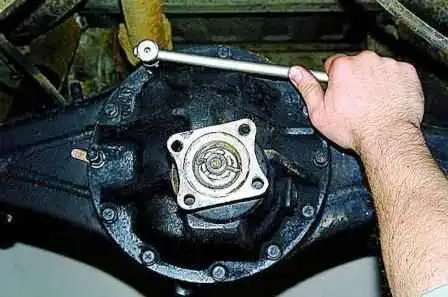
Using a 14 mm spanner or socket, unscrew the ten bolts securing the reducer to the rear axle beam.
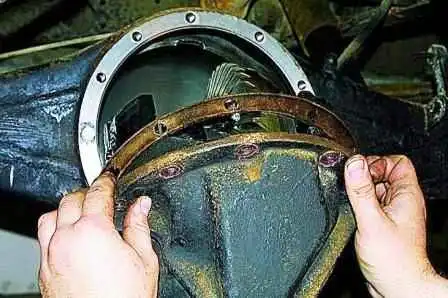
Remove the reducer from the beam, taking care not to damage the sealing gasket.
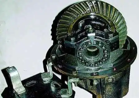
For convenience, mount the reducer on a stand. Remove the drive gear flange together with the oil seal.
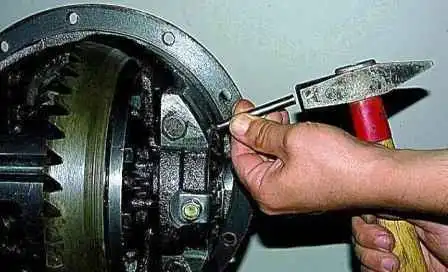
Use a centre punch to mark the relative position of the differential bearing caps, adjusting nuts and housing.
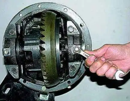
Using a 12 mm spanner, unscrew the bolts of the bearing cap locking plates.
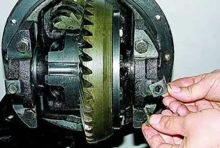
Remove the locking plates.
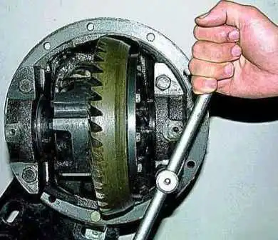
Using a 17 mm spanner or socket, unscrew the bolts securing the bearing caps.
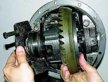
Remove the bearing caps.
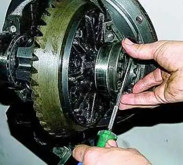
Using a special spanner or a heavy-duty screwdriver, unscrew the differential bearing adjusting nuts.
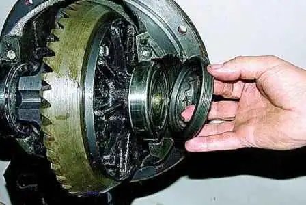
Remove the adjusting nuts.
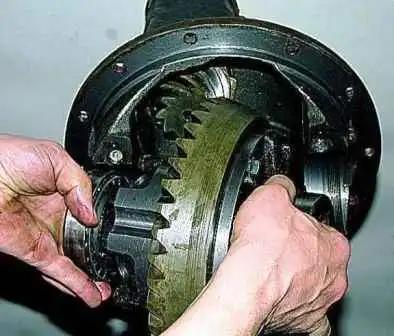
Remove the satellite box assembly together with the driven gear and the bearing outer races.
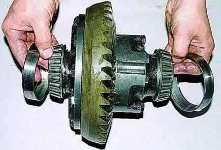
The driven gear is fitted to the satellite box in only one position. To simplify assembly and preserve balance, mark the relative position of the gear and the housing.
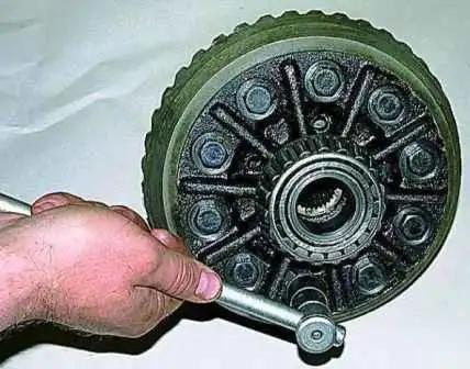
Using a 17 mm spanner or socket, unscrew the 10 bolts securing the driven gear.
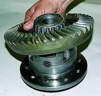
With light hammer blows through a soft-metal drift, knock the gear off the satellite box and remove it.
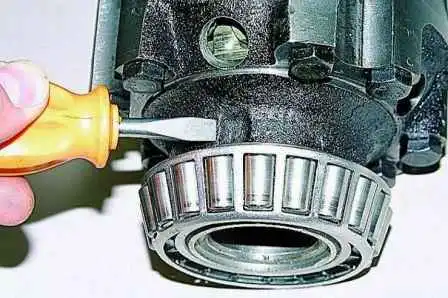
Special recesses are provided on the satellite box for the puller jaws.
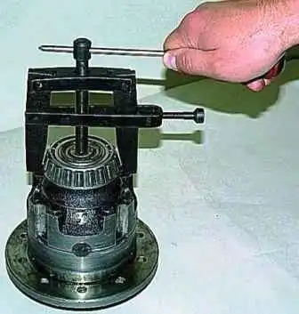
Use a special puller to press off the bearing inner races. Remove the second bearing in the same way.
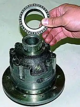
If no puller is available, insert a chisel between the end face of the bearing inner race and the differential box. Striking the chisel, shift the inner race.
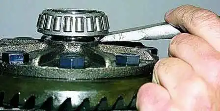
Insert two heavy-duty screwdrivers or pry bars into the resulting gap.
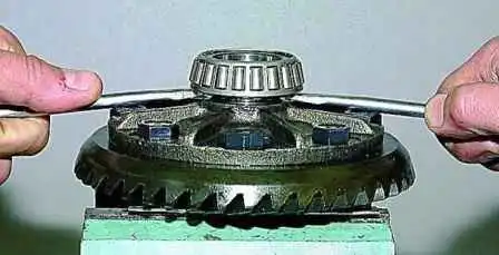
By pressing evenly on the pry bars, press off the bearing inner race together with the cage and rollers.
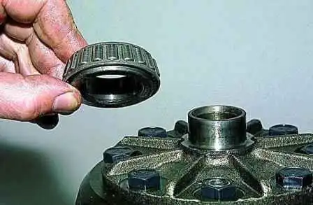
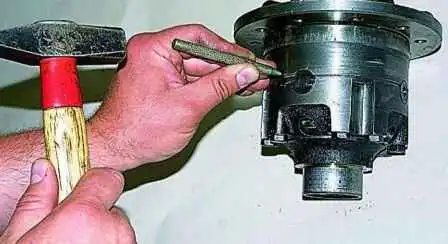
Use a centre punch to mark the relative position of the left and right parts of the differential box.
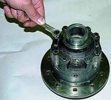
Using a 13 mm spanner, unscrew the eight bolts connecting the differential box parts.
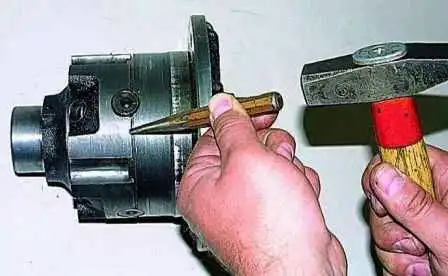
Carefully tapping with a hammer through a soft drift, separate the box.
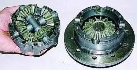
Remove the side gear from the removed half of the box.
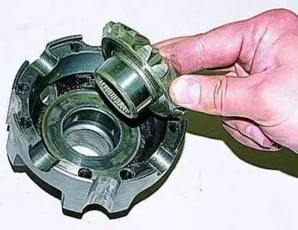
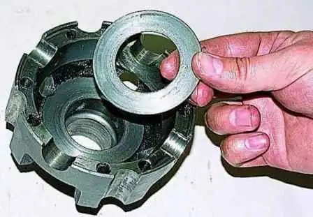
Remove the thrust washer.
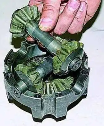
Remove the cross shaft (pinion shaft) assembly with the pinions and their thrust washers.
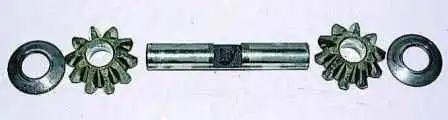
Remove the pinions and washers from the shafts.
Remove the second side gear and its thrust washer.
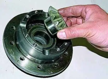
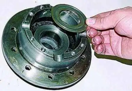
Remove the drive gear from the reducer housing. If necessary, it can be knocked out with hammer blows through a soft-metal spacer on the shaft end.
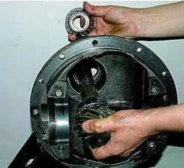
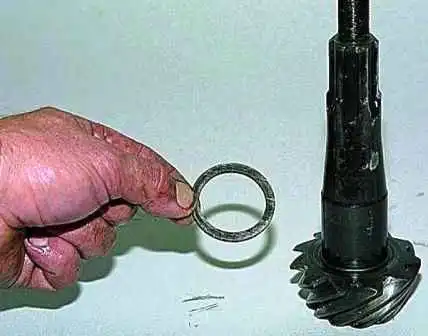
Remove the spacer sleeve (ring) from the drive gear shaft.
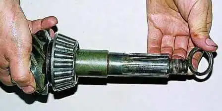
Press the rear bearing inner race off the gear shank.
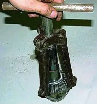
Remove the adjusting shim (ring) that sets the drive gear mesh depth.
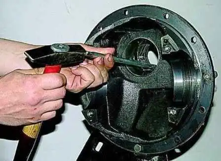
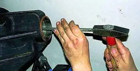
Use a drift to knock the front bearing outer race out of the housing.
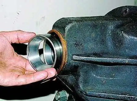
Remove the race. Knock out the rear bearing outer race in the same way.
Before assembly, wash all parts in paraffin or diesel fuel and inspect them thoroughly.
Requirements for the condition of parts:
- No cracks of any kind are permissible on the parts.
- There must be no scuffing, pitting or severe wear on the gear teeth.
- The bearings must rotate freely, without clicks or jamming.
- Pitting, chips and severe wear are not permissible on the rollers and races.
- Bearing cages must not have tears or deformation.
Replace damaged and worn parts. At mileage over 100,000 km, preventive replacement of the bearings is recommended regardless of their visual condition.