


We remove the exhaust manifold when repairing the cylinder head or replacing the manifold gasket.
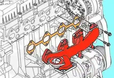
We disconnect the battery negative terminal. The manifold is cast iron, secured to the cylinder head with eight M8 bolts with sleeves; the cylinder head–manifold gasket is a multi-layer metal gasket, and the manifold–turbocharger gasket is metal.
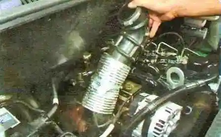
We remove the air filter and the air supply hose (article — Replacing the air filter).
We remove the exhaust gas recirculation valve together with the heat exchanger.
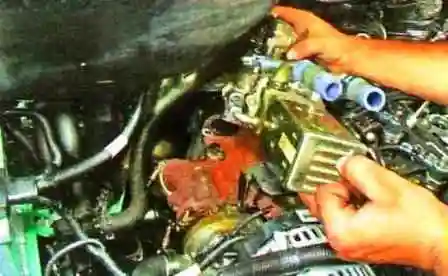
We undo the three nuts and one bolt securing the turbocharger to the manifold.
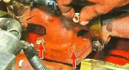
We undo the securing bolt and detach from the manifold the bracket of the recirculation heat exchanger.
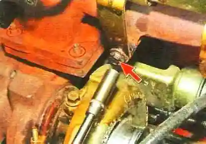
We undo the eight bolts securing the exhaust manifold to the cylinder head.
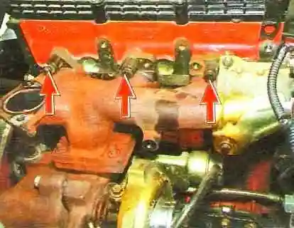
We take the bolts with sleeves out of the holes.
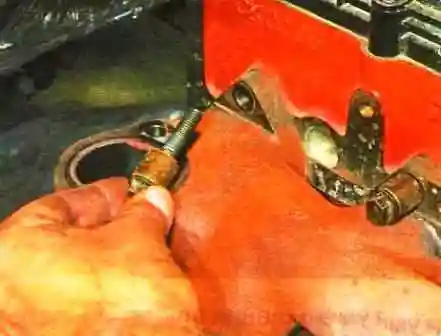
We carefully pull the exhaust manifold upwards.
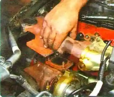
Sliding the exhaust manifold off the mounting studs at the turbocharger flange, we remove it.
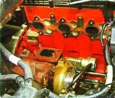
We remove the gasket between the cylinder head and the exhaust manifold.
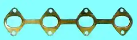
We remove the gasket fitted between the manifold and the turbocharger.
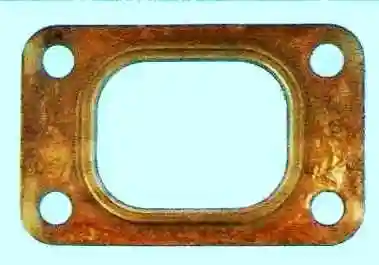
We clean the contact surfaces of the cylinder head and the exhaust manifold.
Using No. 240 abrasive paper, we remove the carbon deposits from the cylinder head contact surface.
We check the parts for the absence of cracks and other damage (if the exhaust manifold is damaged, the charge air cooler must be checked).
A fault in the charge air cooler can cause damage to the exhaust manifold.
Using a straightedge and a feeler gauge, we check the flatness deviation of the exhaust manifold support surfaces.
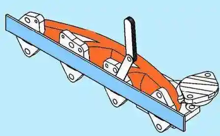
Placing the straightedge over all the holes, we measure the flatness deviation with the feeler gauge.
If the flatness deviation of the exhaust manifold exceeds 0.13 mm, the manifold must be replaced or machined.
We apply graphite grease to the bolt threads.
We fit the gasket and the bolts securing the turbocharger to the exhaust manifold.
We fit the exhaust manifold to the cylinder head and lightly secure it with the bolts.
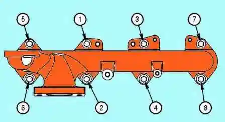
We tighten the exhaust manifold securing bolts in the sequence shown in the figure. Tightening torque: 42 N·m.
We reassemble all parts in the reverse order.
We fill the engine coolant.