


Replacing the cylinder head cover gasket Cummins ISF2.8 (GAZelle NEXT)
The engine cylinder head cover is sealed with a rubber gasket. The injector securing bolts are also sealed with rubber O-rings.
If tightening the bolts has not eliminated the oil leak, the gasket or the rings must be replaced.
Tools and materials required
To replace the gasket you will need: pliers, a 10 mm socket, a plastic trim lever, a flat-blade screwdriver and a torque wrench.
Materials and parts used:
- New cylinder head cover gasket (rubber, profiled). It is recommended to use an original part or a quality equivalent. Before fitting, check the gasket for cracks and hardening of the rubber.
- New injector O-rings (if there is a leak under an injector).
- New O-rings for the injector securing bolts (if there is a leak).
- Engine oil (for lubricating the O-rings before fitting).
- Rags, cleaner for removing remnants of the old gasket and oil contamination from the cover grooves.
Important: the cover securing bolts are tightened in a strictly defined sequence and to a defined torque. The rubber bushes of the cylinder head bolts should not be removed unless necessary.
Preparation and removal
We prepare the vehicle for the work. We disconnect the negative battery terminal.
We remove the exhaust gas recirculation transfer pipe.
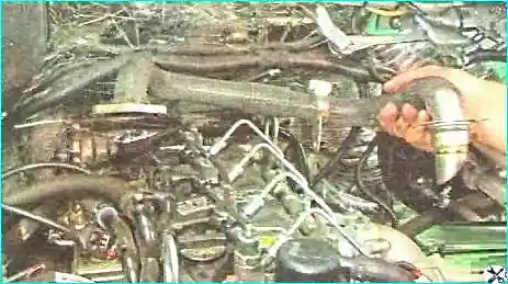
We remove the injectors.
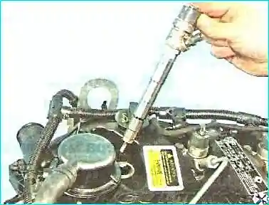
We prise up the wiring harness holder with the plastic trim lever.
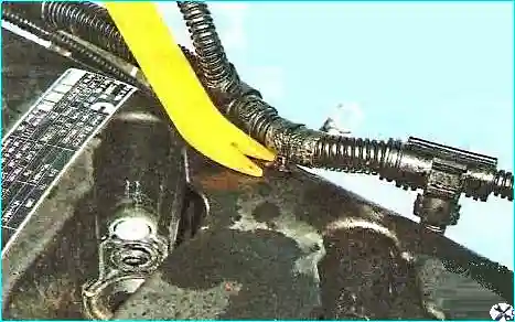
We detach the first holder from the cover.
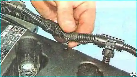
Then we detach the second holder.
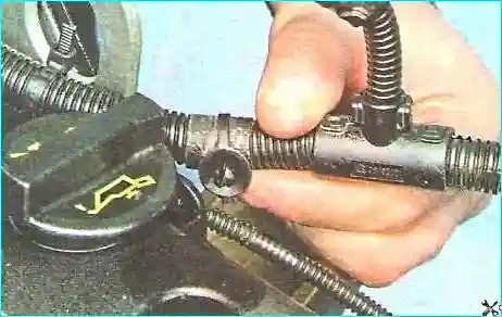
Then we detach the third holder of the injector wiring harness.
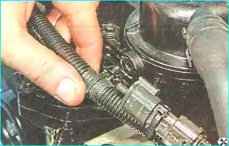
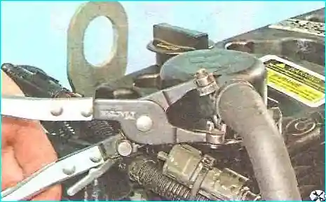
We move the wiring harness aside. We slacken the crankcase ventilation hose clip by squeezing its bent tabs, and slide the clip along the hose.
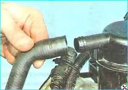
We remove the hose from the crankcase ventilation breather union.
We unscrew the ten bolts securing the cover to the cylinder head.
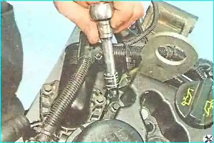
We remove the cover and extract the sealing gasket from the cover grooves.
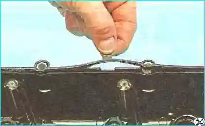
The cylinder head bolts are retained by rubber bushes. They should not be removed unless necessary.
If an oil leak under an injector has been observed, we prise up the edge of its O-ring with a screwdriver and extract the ring from the hole in the cylinder head cover.
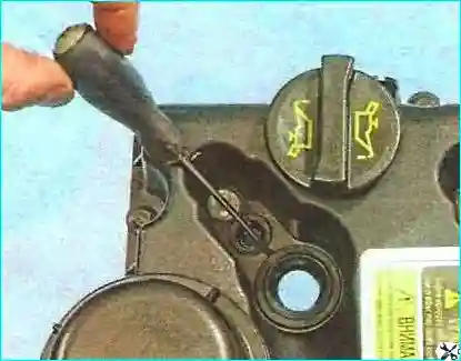
In the same way we extract the remaining injector rings. If necessary, prising them up with a screwdriver.
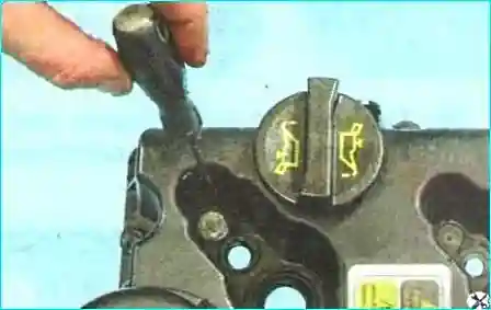
We extract the O-rings of the injector securing bolts from the holes in the cover.
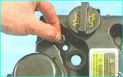
Fitting the new gasket and reassembly
We clean the cover grooves of remnants of the old gasket and fit the new gasket into the cover grooves. The injector and bolt O-rings are lubricated with engine oil to ease fitting.
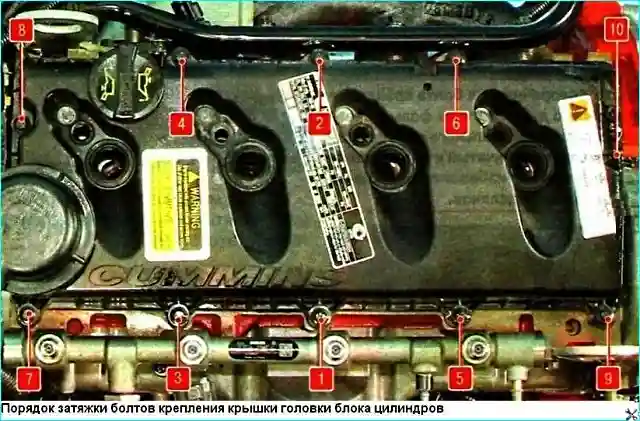
We refit the cylinder head cover and all the parts in the reverse order. The cover securing bolts are tightened to 10 N·m in the order shown in the figure.