


Checking the compression in the engine cylinders Cummins ISF2.8 (GAZelle NEXT)
The most important indicator of the engine condition is the compression in the engine cylinders.
From the average value and the difference between the compression values, the general wear of the connecting rod and piston assembly and the valve mechanism can be determined.
The compression is checked using a compression tester.
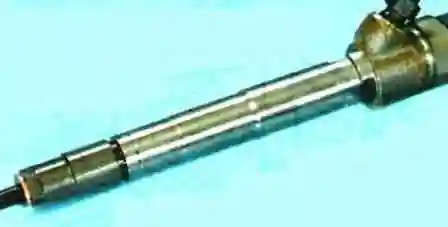
For the Cummins ISF2.8 engine, the compression tester must have an adaptor shaped to match the injector body.
Tools and materials required
To carry out the work you will need: a compression tester with an adaptor shaped to match the injector body, a set of spanners, a compressor hose for supplying compressed air, engine oil, rags.
Materials and parts used:
- New copper injector sealing washers — mandatory replacement when the injectors are removed.
- Clean engine oil (about 20 ml) — to determine the cause of insufficient compression.
- Rags, cleaner for removing contamination from the pipe unions and injectors.
Important: the battery must be charged and the starter motor in good order. Before checking the compression, the engine must be warmed up to operating temperature. The nominal pressure is 2.2 MPa, the minimum permissible pressure is 1.9 MPa, and the pressure difference between cylinders must not exceed 0.3 MPa.
Preparation for the compression check
Before checking the compression, the engine must be warmed up to operating temperature.
We open the bonnet and squeeze the adaptor of the fuel supply pipe to the high-pressure fuel pump.

We disconnect the pipe.

We start the engine and let it run until it stops as a result of the fuel being used up from the high-pressure line.
We clean the unions of the pipes going to the injectors.
We press the catch and disconnect the wiring harness connector from the injector.

We press the catch securing the return pipe union to the injector.

We disconnect the return pipe.

We unscrew the nuts securing the high-pressure pipes and disconnect the pipes from the injectors.

We unscrew the securing bolts and extract them from the holes.

We remove the injector holders.

We remove the injectors and mark them so as not to mix them up on refitting.

The injectors are sealed with copper washers. These washers must be replaced.
Checking the compression
We fit the compression tester into the injector hole and secure its adaptor with the injector securing parts.

We operate the starter and turn the crankshaft until the pressure in the cylinder stops rising.
We record the compression tester reading for this cylinder and measure the pressure in the following cylinders in the same way.
The pressure must be 2.2 MPa.
The minimum permissible pressure is 1.9 MPa.
The pressure difference between cylinders must not exceed 0.3 MPa.
Determining the cause of insufficient compression
To determine the cause of insufficient compression, we pour about 20 ml of clean engine oil into the cylinder with reduced pressure and measure the compression in that cylinder again.
If the compression tester readings increase, this indicates a fault in the piston rings.
If the readings do not change, the valves are not seating properly on their seats or the cylinder head gasket is damaged.
The cause of insufficient compression can also be determined by supplying compressed air into the cylinder in which the piston has first been set to TDC on the compression stroke.
To do this we remove the adaptor from the compression tester and connect the compressor hose to it.
We insert the adaptor into the injector hole and supply air to the cylinder at a pressure of 0.2—0.3 MPa.
So that the crankshaft does not turn, we engage the highest gear and brake the vehicle with the parking brake.
The escape (leakage) of air through the intake pipe indicates a leak at the inlet valve, and through the silencer — a leak at the exhaust valve.
If the cylinder head gasket is damaged, air will escape through the expansion tank neck in the form of bubbles or into the adjacent cylinder, which is detected by a hissing sound.
Reassembly and tightness check
After checking the compression, we refit the parts in the reverse order and bleed the fuel system.
We start the engine and check the tightness of the fuel system connections.