


In this article, we will look at how to remove the half-shaft, replace and adjust the rear wheel hub bearings.
Removing the rear wheel drive half-shaft
We prepare the vehicle for the task.
We position the vehicle on a lift or in an inspection pit.
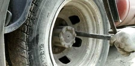
We loosen the rear wheel nuts on the side being worked on.
We jack up the rear wheels on the side being worked on.
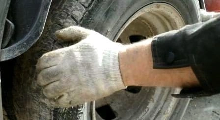
We unscrew and remove the wheels on the side being worked on. Note: it is not strictly necessary to remove the wheels to extract the half-shaft, but doing so greatly facilitates the operation.
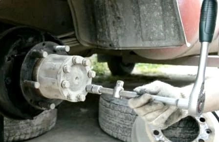
Using a 19 mm socket, we unscrew the eight bolts securing the half-shaft to the wheel hub.
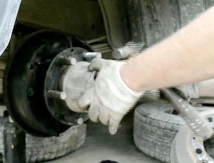
With light hammer blows on the half-shaft flange (using a wooden or brass spacer), we break it free from its seat.
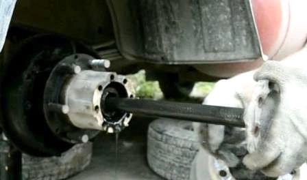
We place a container under the hub to catch the draining oil and carefully pull the half-shaft out of the axle housing.
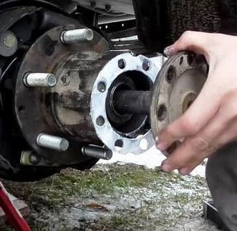
We install the half-shaft in reverse order. It is advisable to coat the cardboard gasket with a thin layer of sealant on both sides to prevent leaks.
We tighten the half-shaft mounting bolts to a torque of 90–125 N·m. We check and, if necessary, restore the level of transmission oil in the rear axle housing (see article – Checking and replacing the oil).
Replacing the wheel bearings and half-shaft oil seal
We release the handbrake, placing chocks under the front wheels.
We remove the rear wheels on one side of the vehicle and extract the half-shaft as described above.
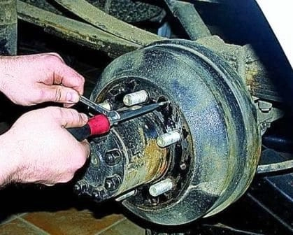
We unscrew the three screws securing the brake drum (if seized, the use of an impact screwdriver is recommended).
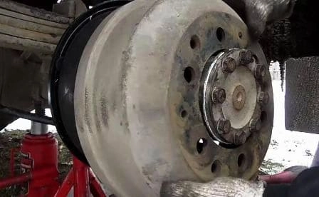
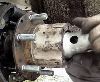
Using the special 62 mm spanner from the standard kit, we unscrew the outer locknut.
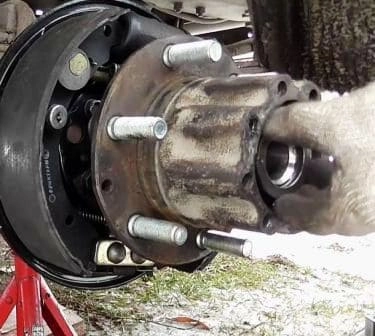
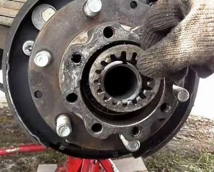
We extract the lock washer by carefully prying it up with a hook or two screwdrivers.
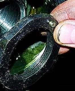
Using the same spanner, we unscrew the inner adjusting nut and remove it. Attention: when installing, it must be positioned with the pin facing outwards (towards the lock washer side).
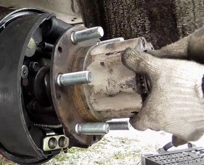
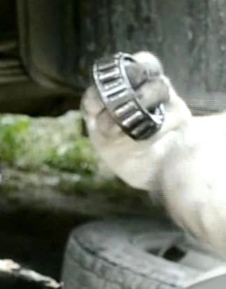
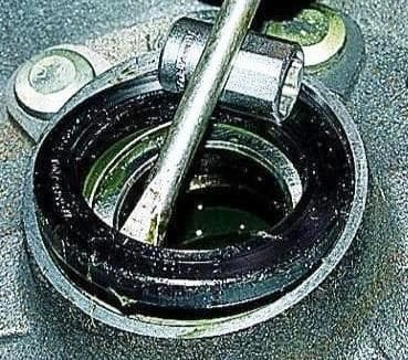
We carefully pry out and remove the oil seal. It is recommended to replace the oil seal with a new one every time the hub is removed.
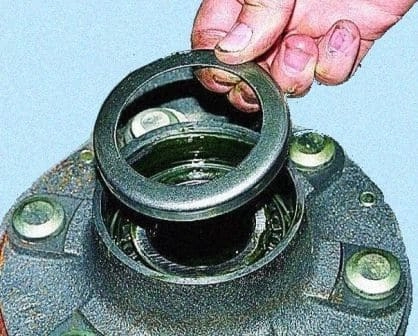
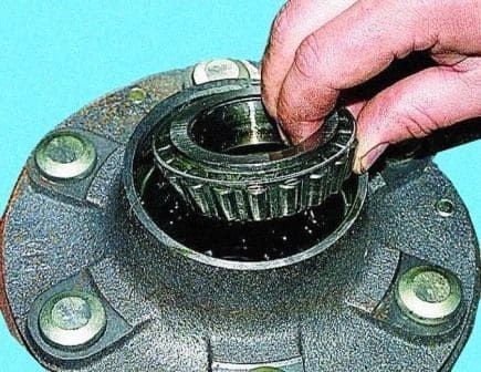
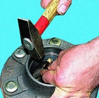
Using a soft metal drift (aluminium or brass), we drive out the outer races of the outer and inner bearings.
We thoroughly wash the internal cavity of the hub and other parts with paraffin or diesel fuel, then blow them dry with compressed air.
Assembly:
We lubricate the bearing seats with clean transmission oil. Using hammer blows via a soft spacer (or a suitable diameter sleeve), we press in the outer races of the new bearings.
We generously pack the rollers and cage of the inner bearing with plastic grease (e.g. Litol-24 or Shell Alvania RL3) and insert its inner ring into the outer ring.
Having fitted the thrust washer and lubricated the lips of the new oil seal with Litol-24 grease, we press in the new oil seal using the old oil seal as a pressing tool.
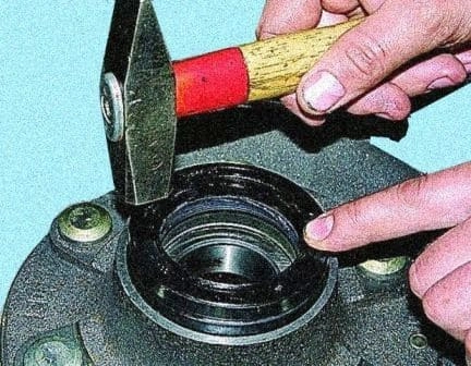
We slide the hub onto the half-shaft housing, then install the inner ring with the Litol-24 lubricated rollers of the outer bearing.
We screw in the adjusting nut and proceed to adjust the bearings. We install the half-shaft, then fill the hub and axle with oil (see Checking and replacing the oil).
Adjusting the wheel bearings
We jack up the rear axle until the wheels leave the ground and remove the wheels.
We remove the half-shaft (to access the nuts).
We unscrew the outer nut, remove the lock washer, and loosen the inner bearing nut by ⅓ of a turn.
We check the free rotation of the hub. If the brake shoes are rubbing against the drum, we rectify this fault before repeating the adjustment.
We tighten the bearing nut with the special spanner to a torque of 20–25 N·m (2.0–2.5 kgf·m), continuously rotating the hub to ensure the rollers self-align correctly.
We then back off the nut by an angle of 22–45° (1 to 2 slots on the lock washer, no more) to create the necessary thermal clearance.
We fit the lock washer so that the nut's locking pin engages the nearest slot.
We fit and tighten the outer locknut to a torque of 150–200 N·m (15–20 kgf·m) using the same spanner.
After this, the hub must rotate freely, without play, clicking, or binding.
We install the remaining parts in reverse order and fill the hub with oil.
Adjustment check: We drive the vehicle for approximately 10 km. Heating of the hub above 70° C (the hand cannot bear to touch it) is considered unacceptable and requires re-adjustment by reducing the initial tightening torque.