The sensors of the engine control system during engine operation and when the engine is started constantly monitor and maintain the set parameters and transmit signals to the electronic control unit
Removing and installing the crankshaft position sensor
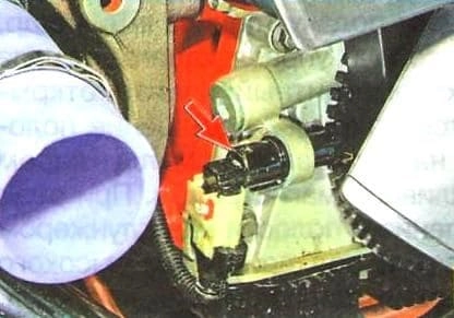
The sensor is installed in the front cover of the cylinder block on the right side.
If the crankshaft position sensor fails, the engine will not start.
If the sensor works intermittently, (bad start or interruptions in engine operation), you need to check for foreign particles on the magnetic end of the sensor.
If foreign particles are present, clean the sensor.
To remove the sensor, you will need a flat-blade screwdriver and a 5" hex key.
Disconnect the negative battery terminal.
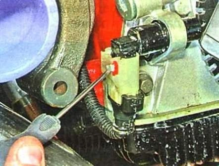
We move the locking plate of the wiring harness block with a screwdriver
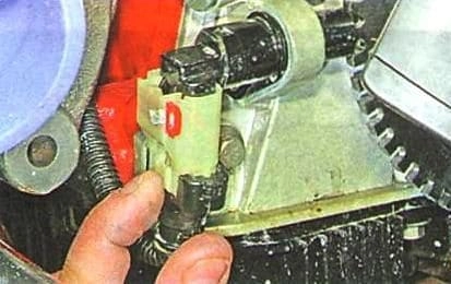
Squeeze the latch
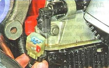
Disconnect the wiring harness block from the crankshaft position sensor
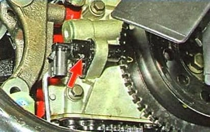
Remove the sensor mounting screw
Remove the sensor.
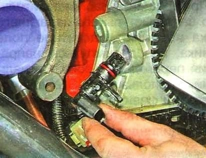
Install the new crankshaft position sensor in reverse order. Bolt tightening torque 8 Nm.
Camshaft position sensor
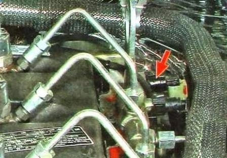
The camshaft sensor is installed in the hole of the upper casing of the timing chain, in the rear of the engine on the left side.
If the camshaft sensor stops working, then the controller uses only the crankshaft sensor signals.
Required - a screwdriver and a hexagon wrench for 5.
Disconnect the negative battery terminal
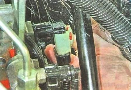
We move the stopper of the wire block.
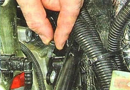
Squeeze and disconnect the block of wires from the sensor
Unscrew the sensor mounting screw (DPRV)
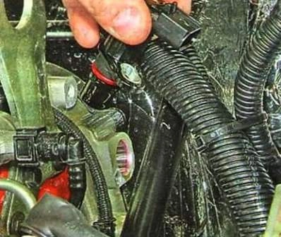
Remove the camshaft position sensor.
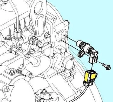
Install the sensor in reverse order.
Lubricate the O-ring with clean engine oil. Screw tightening torque 8 Nm.
Combined boost pressure/intake manifold air temperature sensor
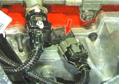
Pressure and air temperature sensors in the intake manifold are combined into a single unit.
The sensor is mounted on top of the engine intake pipe.
If the combination sensor is faulty, the controller limits the boost pressure and the engine power is reduced.
Disconnect the negative battery terminal
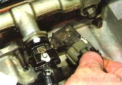
Squeeze the wire block retainer
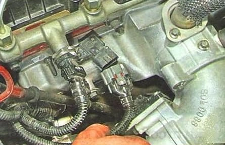
Disconnect the wiring harness from the sensor
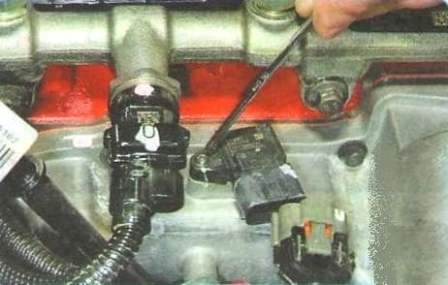
Unscrew the screw that secures the combined sensor.
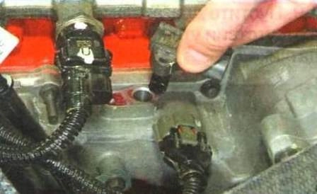
Remove the sensor from the engine by pulling it vertically up.
When removing the probe, be careful not to damage the O-ring and the plastic guard surrounding the probe tip.
Do not use the lever to avoid damaging the plastic guard.
Check the wiring harness connector and combined sensor for the following defects:
- - cracks or damage on the hull;
- - missing or damaged connector seals;
- - dirt, foreign particles or moisture on connector pins;
- - corroded, bent, broken, depressed or expanded connector pins.
Check the sensor tip for the absence of soot and deposits, soot.
If necessary, remove soot with compressed air.
Do not replace the sensor due to soot.
Install the sensor on the engine. We tighten the bolt with a torque of 6 Nm.
Atmospheric pressure sensor
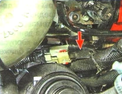
The sensor is attached to the wiring harness without attaching it to the engine with bolts, on the left side.
If the sensor fails, the controller will bypass using the estimated average barometric pressure.
Disconnect the negative battery terminal
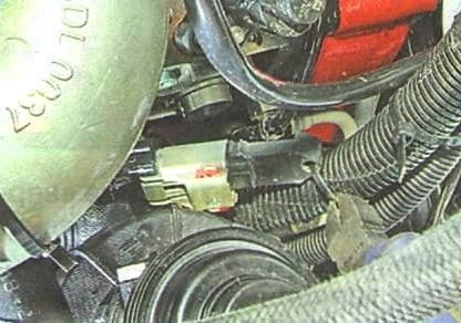
We bite the clamp securing the atmospheric pressure sensor to the engine wiring harness
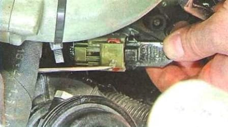
Move the retaining bar of the wiring harness block
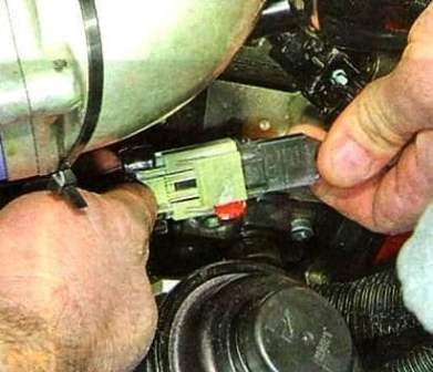
Squeeze the latch
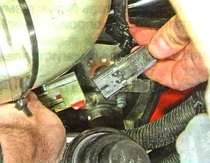
Disconnect the atmospheric pressure sensor from the block
You can only check the sensor with a diagnostic tester.
We install the atmospheric pressure sensor and attach it to the engine wiring harness with a new clamp.
Fuel pressure sensor
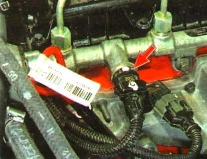
The fuel pressure sensor is located on the rail, screwed into the hole. If the fuel pressure sensor fails, the injection pump does not work.
To remove the sensor, you need to release the pressure not in the fuel line.
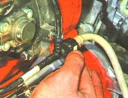
Squeeze the latch of the tip of the fuel supply pipe to the injection pump
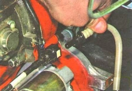
Disconnecting the pipeline.
We start the engine and let it run until it stops completely (thus, we relieved the pressure in the fuel line).
Disconnect the negative battery terminal
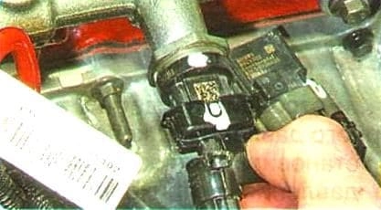
Squeeze the latch
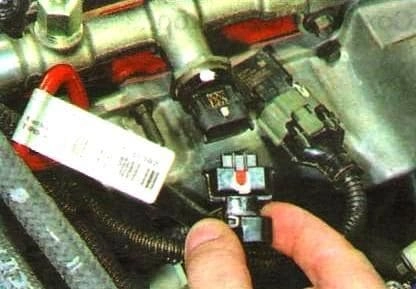
Disconnect the wiring harness from the fuel pressure sensor
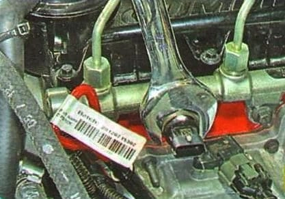
Using a 27 key, we unscrew the sensor from the fuel rail
Inspect the connector and the sensor itself for the following defects:
- - cracks or damage on the connector body;
- - missing or damaged connector seals;
- - dirt, foreign particles or moisture on connector pins;
- - corroded, bent, broken, depressed or expanded connector pins.
Check the fuel pressure sensor for the following damage:
- - damage to the contact surface on the fuel line;
- - damage to the contact surface on the sensor;
- - thread damage.
Installing a new fuel pressure sensor. Sensor tightening torque 70 Nm.
We start the engine and check the tightness of the sensor connection.
Replacing the coolant temperature sensor
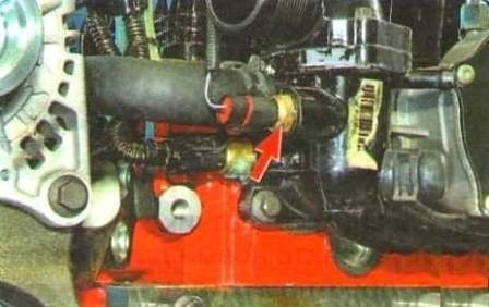
The coolant temperature sensor, designed to detect the temperature of the coolant in the engine, is installed in the thermostat housing boss, located closer to the cylinder block.
The second sensor, installed in the thermostat housing boss closer to the radiator, serves to operate the coolant temperature gauge in the instrument cluster.
The control unit, according to the readings of the coolant temperature sensor, changes the moment the fuel injection starts and controls the air heater in the intake pipe.
If a sensor fault occurs, the controller takes the average temperature value.
Preparing the car for work.
Disconnect the negative battery terminal.
Removing the accessory drive belt Cummins ISF2.8 Accessory Drive Belt Replacement
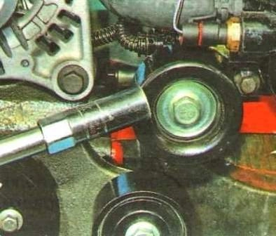
We unscrew the bolt securing the upper intermediate roller to the cylinder head
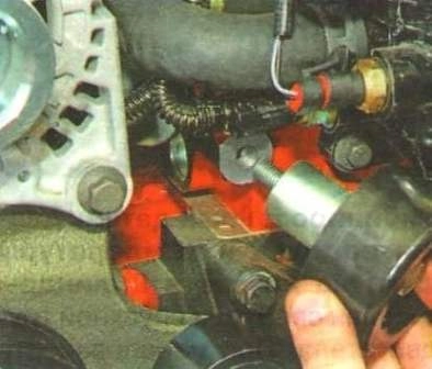
Shooting a video
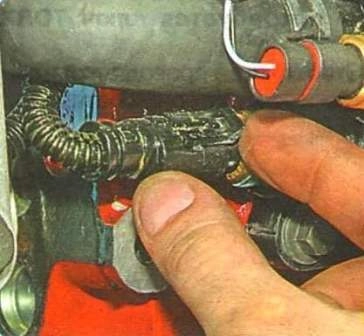
Press out the latch
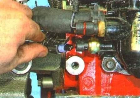
Disconnect the wiring harness from the coolant temperature sensor
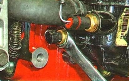
Unscrew the sensor
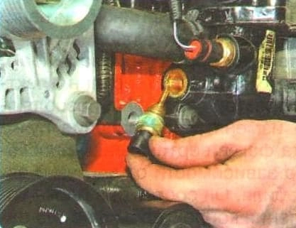
Remove it from the threaded hole in the thermostat housing
After unscrewing the sensor, immediately insert the plug or screw in a new sensor so as not to drain the coolant.
Install the new sensor in reverse order. The rubber sealing ring must be replaced with a new one.
Before connecting the wire block, you need to carefully inspect it for defects.


