


Cummins ISF2.8 engine oil pump (GAZelle Next)
The oil pump housing is a single casting with the cylinder block front cover. If the pump needs to be replaced, the cover is replaced as an assembly.

To carry out the work you will need: 10, 12, 14, 17 and 32 mm spanners; 12 and 16 mm sockets; a set of screwdrivers; an oil filter wrench; pliers; a drain pan for the oil; oil-resistant sealant.
Prepare the vehicle: position it over an inspection pit.
Drain the engine oil (see the article “Oil and oil filter replacement”).
Drain the coolant from the cooling system.
Remove the radiator.
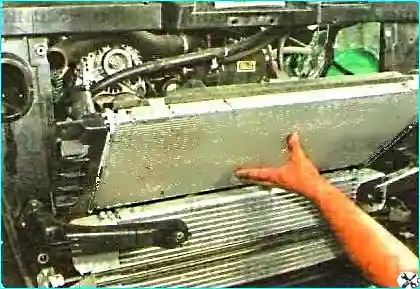
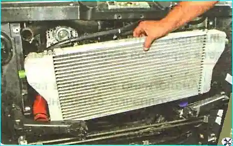
Remove the charge-air cooler (intercooler).
Unscrew the viscous coupling from the support spindle and remove it together with the fan. Disconnect the wiring connector from the crankshaft position sensor.

Remove the auxiliary drive belt (see the article “Auxiliary drive belt replacement”).
Unscrew and remove the oil sump (see the article “Sump seal replacement Cummins ISF2.8”).
Unscrew the banjo bolt securing the end fitting of the oil supply hose to the turbocharger bearing.

Disconnect the hose from the front cover housing.

Slacken the clamp securing the pipe from the cooler to the intake pipe, disconnect the pipe and move it aside.

Squeeze the bent lugs of the heater hose clamp, slide the clamp along and disconnect the hose from the front cover union.

Squeeze the lugs of the expansion tank hose clamp, slide it along and disconnect the hose from the union.

Disconnect the wiring connector from the low oil pressure warning sensor.

Unscrew the three crankshaft pulley bolts.

Remove the washer and the pulley.

Unscrew the ten securing bolts.

Remove the front cover as an assembly by pulling it forwards.

When removing the front cover, it must be moved strictly along the engine axis, otherwise the front crankshaft oil seal may be damaged.

The union 7 (Fig. 1) connecting to the cylinder block cooling jacket is sealed with a rubber ring and fitted into the block bore with interference, so force must be applied to extract it.
Remove the front cover gasket.
Refit the front cover in the reverse order.
Before fitting the new gasket, apply a thin layer of oil-resistant sealant to both sides of the lower ends of the gasket.

Fit a new sealing ring on the union connecting to the cylinder block cooling jacket and thoroughly clean the walls of the bore in the block.

Before fitting the cover, lubricate the rubber sealing ring on the cover housing and the walls of the bore in the block with coolant.
Before fitting the cover to the block, pour clean engine oil through channel 9 (Fig. 1). Rotate the pump gears by the internal gear hexagon so that the oil flows into the internal cavities of the pump.
To ease fitting the seal onto the crankshaft, lubricate the working surface of the front end of the shaft with engine oil.

Fit the front cover and the remaining parts in the reverse order.
Tighten the bolts securing the front timing gear cover to the cylinder block in the order shown in the figure. Tightening torque 24 N·m.

Fill the engine lubrication system with oil.
Materials used and recommendations
Front cover gasket — oil-resistant paronite or multi-layer metal; sealant — anaerobic oil-resistant; union sealing ring — heat-resistant rubber; crankshaft oil seal — rubber with a garter spring; fasteners — grade 8.8 bolts (tightening torque 24 N·m). Before assembly, check that channel 9 is clean and that there are no metal chips in the internal cavities of the pump.