Install the gearbox on a workbench or stand
Before disassembling, let's analyze the gearbox's faults
Main symptoms of gearbox faults and how to troubleshoot them
Noise or crackling when shifting gears:
- - check the oil level and its quality;
- - check the condition of the gearshift drive;
- - check the synchronizers and their hubs.
One or more gears do not engage:
- - check the oil level and its quality;
- - check the condition of the gearshift drive;
- - check the synchronizers.
- - check the gearshift forks and their locks.
Spontaneous Gear shifting:
- - Check the condition of the powertrain mounts;
- - Check the condition of the gearshift drive;
- - Check the synchronizers and their hubs.
- - Check the gearshift forks and their latches.
One or more gears are locked:
- - Check the condition of the powertrain mounts;
- - Check the condition of the gearshift drive;
- - Check the synchronizers and their hubs.
- - Check the gearshift forks and their latches.
- - Check the condition of the gear pinions.
Noise in the gearbox:
- - Check the oil level and its quality;
- - Check the condition of the gearbox bearings;
- - Check Condition of the gears.
Remove the clutch slave cylinder mounting bolts (Fig. 1)
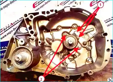
Fig. Fastening the clutch slave cylinder, NDO gearbox: 1 - pipeline fastening bolts, 2 - clutch cylinder fastening bolts.
Remove the gear selector mechanism thrust pin (1), neutral sensor and reverse light switch (3), and the gear selector mechanism ball detent (2) (Figure 2).
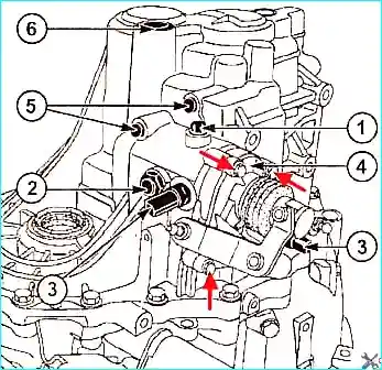
Fig. Gearbox Disassembly: 1 - Gear selector pin, 2 - Gear selector ball detent, 3 - Neutral sensor and reverse light switch, 4 - Gear selector mount, 5 - Shift fork rod retainers, 6 - Cap.
Also, remove the mechanism mounting screws (shown with red arrows) and remove the mechanism assembly.
Remove the shift fork rod retainers (5) and cap (6).
Remove the transmission case to the clutch housing mounting bolts.
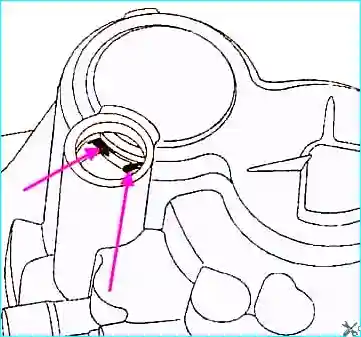
Fig. Location of the secondary shaft retaining ring
Spread the secondary shaft bearing retaining ring (Fig. 3)
Next, remove the gearbox housing.
Remove the gear selector rod retainers (Fig. 4)
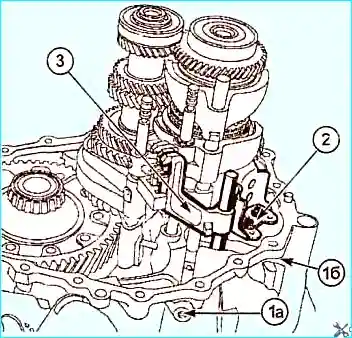
Fig. Gearbox assembly: 1a - large stopper and spring, 1b - smaller stopper and spring, 2 - reverse fork travel limiter, 3 - reverse gear rod and linkage
After this, remove the reverse fork limiter (2) (Fig. 4)
Remove the reverse gear rod and linkage (3)
Remove the two locking pins
Knock them out with a punch (or a valve, as we used when disassembling the JH3 Gearbox) if you have a device, as in Fig. 5, remove the pin securing the 5th and 6th gear shift forks gears.
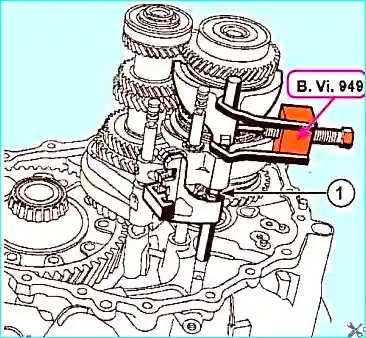
Fig. 1 - Thrust half ring
Remove the thrust half rings of the 5th and 6th gear shift linkage (1) and remove the rod-fork assembly.
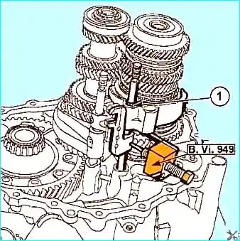
Remove the push rod from the 5th and 6th gear shift rod and the two detent balls.
Remove the thrust half ring of the 3rd and 4th gear shift fork (see 1, Fig. 6).
Using the tool, remove the 3rd and 4th gear shift rod mounting pin.
Remove the 3rd and 4th gear shift rod assembly with the fork.
Remove the push rod from the 3rd and 4th gear shift rod.
Remove the pin from the 1st and 2nd gear shift fork.
Remove the 1st and 2nd gear shift fork and rod assembly and the reverse gear fork and rod assembly travel.
With the help of an assistant, remove the "primary shaft - secondary shaft - reverse idler gear shaft" assembly.


