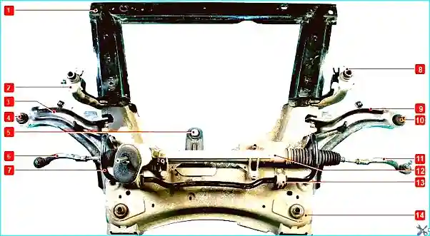
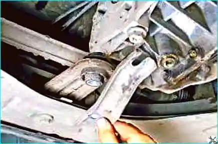
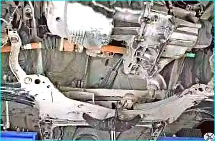
The subframe is a structural component of the front suspension to which the lower front suspension arms, steering gear and lower engine mount are attached.
The subframe consists of two parts: front and rear.
The subframe component layout is shown in Figure 1.
To remove the subframe, the following tools are required: 10, 16, 18 mm spanners, 16, 18 mm sockets, flat screwdriver.
Removing the front subframe section
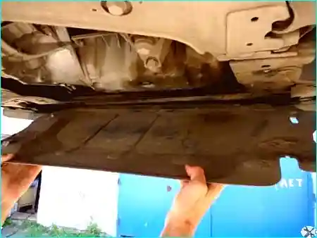
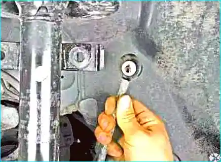
Fig. 2. Remove the undertray and engine splash shield
Remove the front wheel arch liners.
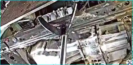
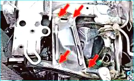
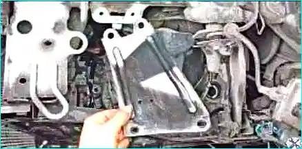
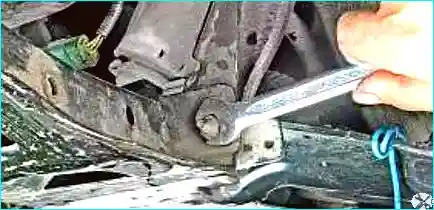
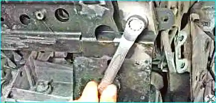
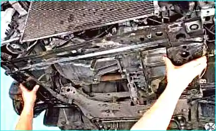
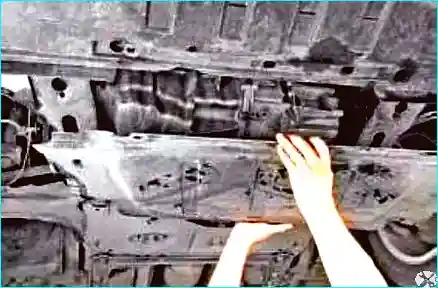
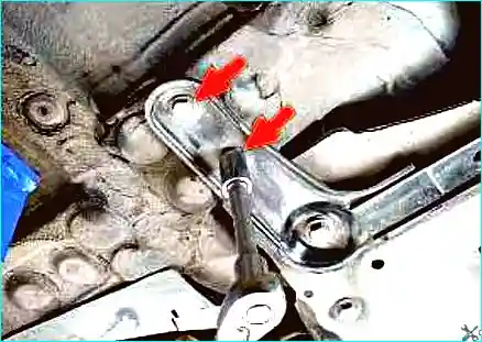
Fig. 3. Place a support under the front subframe sectionFig. 4. Remove the four bolts securing the front subframe section bracket to the bodyFig. 5. Remove the bracketFig. 6. Unscrew the nut securing the front subframe section to the rear subframe sectionFig. 7. Remove the bolt securing the front subframe section to the body. Repeat the same procedure on the other sideFig. 8. Remove the front subframe section
Removing the rear subframe section
Disconnect the negative battery terminal.
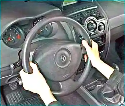
Fig. 9. Set the steering wheel to the straight-ahead position
Apply the parking brake and place chocks under the rear wheels.
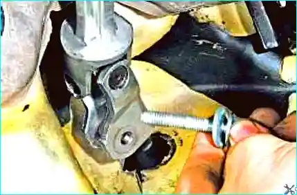
Fig. 10. Unscrew the clamp bolt of the universal joint coupling between the intermediate shaft and the steering gear pinion shaft
Loosen the front wheel bolts.
Raise the front of the vehicle and support it on axle stands.
Fig. 11. Remove the engine undertray
Remove the front wheel arch liners.
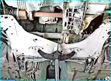
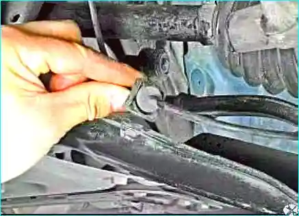
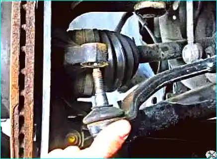
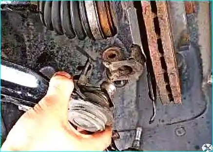
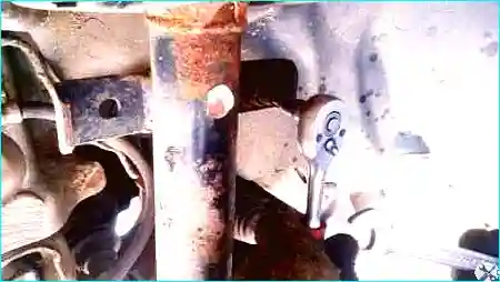
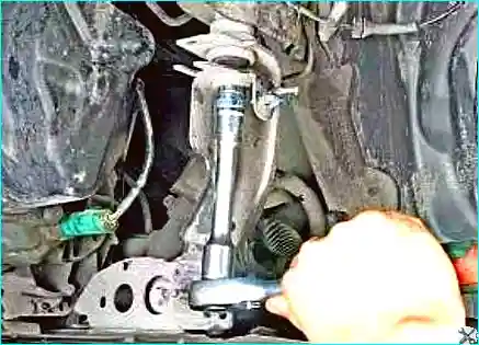
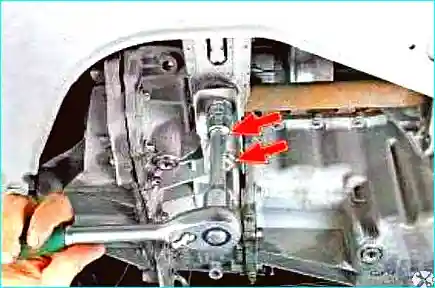
Fig. 12. Place a support under the rear subframe sectionFig. 13. Remove the wheel speed sensor wiring harness holder from the front suspension armFig. 14. Remove the track rod end ball joint pin from the steering knuckle (article – How to replace track rod ends on Renault Megane 2)Fig. 15. Remove the front suspension arm ball joint pin from the steering knuckleFig. 16. Remove the upper anti-roll bar link joint from the strut bracketFig. 17. Remove the two bolts securing the rear subframe section bracketFig. 18. Remove the bolt securing the left rear subframe section bracket to the body. Repeat the same procedure on the other sideFig. 19. Remove the two bolts securing the engine mount bracketFig. 20. Remove the bracketFig. 21. Remove the rear subframe section by lowering it on the standsFig. 22. Rear subframe section
Install the subframe sections and all components in the reverse order.
Torque specifications
Track rod end nut to steering knuckle — 37 N·m;
Universal joint clamp bolt — 21 N·m;
Ball joint pin nut — 62 N·m;
Subframe bolts — 105 N·m;
Subframe nuts — 21 N·m;
Anti-roll bar link nut to suspension arm — 14 N·m;
Wheel bolts — 105 N·m.
For other threaded connections, the torque specifications are as follows: