


The cylinder head is installed after repair, inspection and defect checking.
Before installing the cylinder head, position the cylinder pistons at mid-stroke.
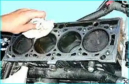
Degrease the mating surfaces of the cylinder head and cylinder block.
Using a screwdriver and a wrapped rag (Fig. 2), remove oil or coolant from the threaded holes of the cylinder head bolts that may have entered during cylinder head removal.
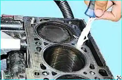
Check for the presence of the guide bush on the cylinder block.
Install the Mot.104 tool or a cut stud as a second guide on the cylinder block.
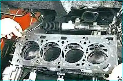
Install the cylinder head gasket on the cylinder block.
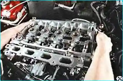
Install the cylinder head. Unscrew the Mot.104 tool or the cut stud used as a second guide.
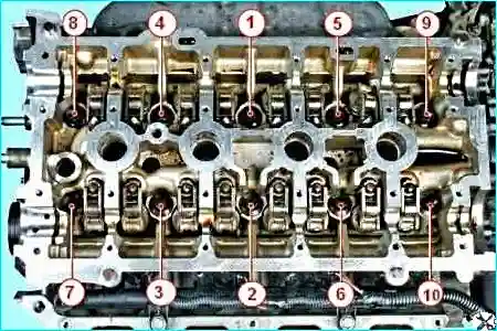
Tighten the cylinder head bolts in the sequence shown in Figure 5 to 20 ± 2 N·m.
After tightening, further tighten all bolts in the indicated sequence by 240 ± 6°.
Install the hydraulic valve lash adjusters (Fig. 6).
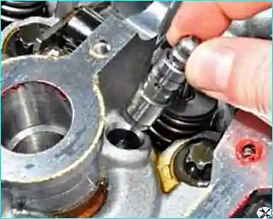
Check the operation of the hydraulic tappets: press on the upper part of the tappet; if the plunger moves in easily, the tappet may be clogged with resins.
Submerge the hydraulic tappet in kerosene or diesel fuel to dissolve the resins.
After this, submerge the tappet in oil and check again.
If the hydraulic lash adjuster does not become elastic, it is faulty and must be replaced.
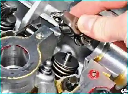
Install the rocker arms (Fig. 7).
Lubricate the camshaft bearings with engine oil.
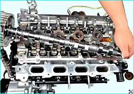
Install the camshafts (see information on camshaft installation).
Degrease the mating surface of the cylinder head and cylinder head cover.
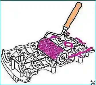
Apply Loctite 518 sealant using a roller until it becomes reddish in colour.
If sealant has got onto the camshaft bearings, wipe it off immediately.
Install the cylinder head cover.
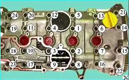
Tighten the cylinder head cover in the sequence shown in Figure 10, in stages:
- 1st stage – bolts 22, 23, 20 and 13 to 8 N·m (0.8 kgf·m);
- 2nd stage – bolts 1–12, 14–19, 21 and 24 to 15 N·m (1.5 kgf·m);
- 3rd stage – loosen bolts 22, 23, 20 and 13;
- 4th stage – tighten bolts 22, 23, 20 and 13 to 15 N·m (1.5 kgf·m).
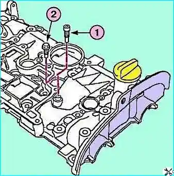
Unscrew the locking bolt (1) of the eccentric cam tappet from tool Mot. 1669 (see Fig. 11).
Screw in the standard locking bolt (2) of the eccentric cam tappet, applying a drop of Loctite Frenetanch to its thread.
Tighten the locking bolt of the eccentric cam tappet to 15 N·m.
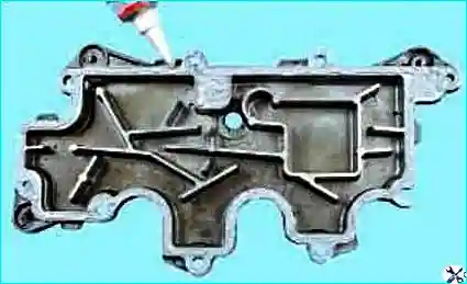
Apply Loctite 518 sealant to the mating surface of the oil separator cover (Figure 12).
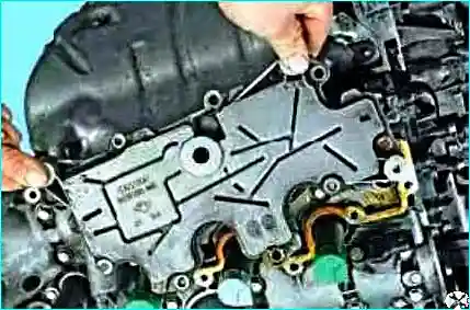
Install the oil separator cover.
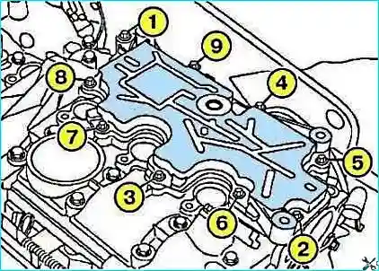
Tighten in the specified order with the required torque the new oil separator bolts in non-threaded holes, and new or existing oil separator cover bolts in threaded holes (see Fig. 14).
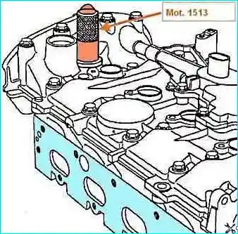
Install the seal of the camshaft phaser solenoid valve using the Mot1513 tool (see Fig. 15) and the intake camshaft phaser solenoid valve.
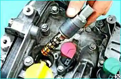
Tighten the intake camshaft phaser solenoid valve bolts to 10 N·m.
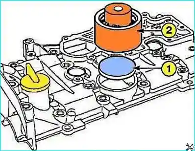
Install the cylinder head cover plug (1) using tool (2) Mot. 1503 (Figure 17).
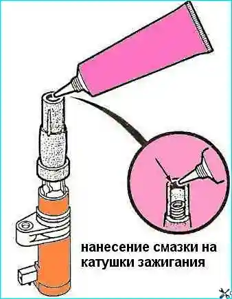
Apply Graisse Fluore grease to all four ignition coils (strip width 2 mm) on the inner circumference of the high voltage wire cap (Figure 18).
Install the spark plugs.
Install the ignition coils in place.
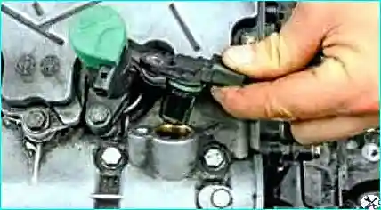
Install the camshaft sensor with a new gasket (Figure 19).
Install the intake manifold gaskets and install the intake manifold.
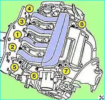
Tighten the intake manifold according to Figure 20.
Continue assembly in the reverse order of removal.
Torque specifications for cylinder head installation:
- Cylinder head cover bolts 1 to 12, 14 to 19 and 21 to 24 — 15 N·m;
- Cylinder head cover bolts 13, 20, 22, 23 — 15 N·m;
- Eccentric cam tappet locking bolt — 15 N·m;
- New oil separator bolts in non-threaded holes — 15 N·m;
- New or existing oil separator bolts in threaded holes — 10 N·m;
- Intake camshaft phaser solenoid valve bolt — 10 N·m;
- Spark plugs — 25–30 N·m;
- Ignition coil mounting bolts — 15 N·m;
- Camshaft sensor mounting bolt — 10 N·m;
- Intake manifold mounting bolts — 9 N·m;
- Timing belt idler pulley bolt — 45 N·m;
- Timing belt tensioner pivot nut — 27 N·m;
- TDC pin hole plug — 20 N·m;
- Upper timing cover bolts — 41 N·m;
- Throttle body bolts — 11 N·m;
- Lifting eye bolts (flywheel side) — 10 N·m;
- Lifting eye bolts (timing side) — 35 N·m.


