


Place the vehicle on a two-post lift.
Remove the upper engine covers.
Remove the front wheels.
Remove the left and right wheel arch liners.
Remove the engine sump guard.
Drain the oil from the gearbox.
Drain the engine oil.
Relieve the fuel pressure in the fuel system.
Disconnect the battery.
Recover the refrigerant from the air conditioning circuit using a recovery station.
Remove the front suspension subframe.
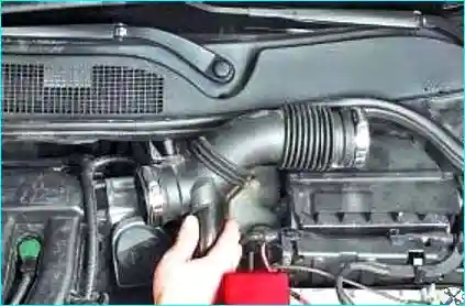
Fig. 1. Remove the air intake hose
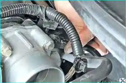
Fig. 2. Release the vacuum booster hose clip
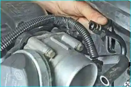
Fig. 3. Disconnect the hose from the intake manifold connector
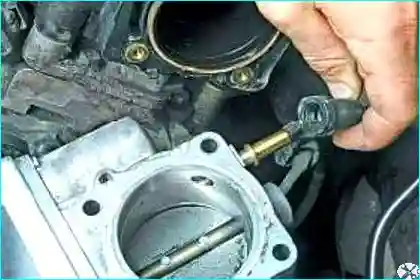
Fig. 4. Disconnect the canister purge valve hose from the throttle body connector
Release the throttle position sensor wiring connector clip.
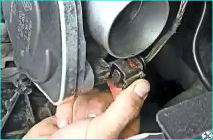
Fig. 5. Disconnect the connector
Release the fuel injector wiring connector clip.
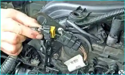
Fig. 6. Separate the connectors
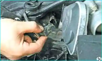
Fig. 7. Release the clip and disconnect the wiring connector from the camshaft position sensor
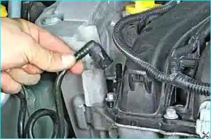
Fig. 8. Disconnect the fuel line hose from the fuel rail connector
Release the camshaft phaser wiring connector clip.
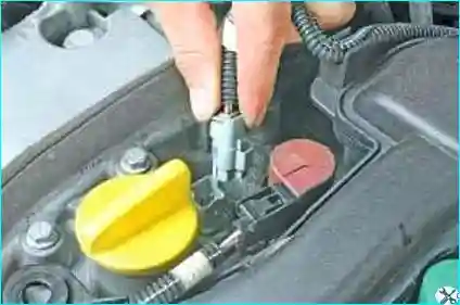
Fig. 9. Disconnect the connector from the phaser
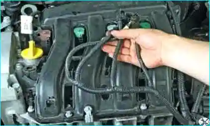
Fig. 10. Disconnect the wiring harness connectors from the ignition coils
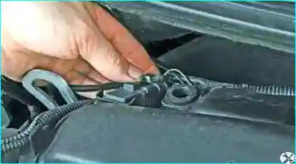
Fig. 11. Release the clip of the manifold absolute pressure sensor wiring connector in the intake manifold
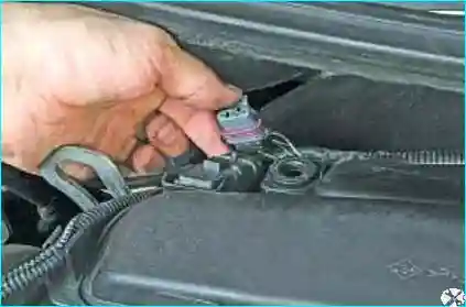
Fig. 12. Disconnect the connector from the sensor
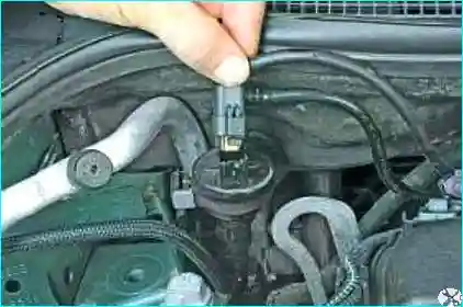
Fig. 13. Release the clip and disconnect the connector from the canister purge valve
Release the intake air temperature sensor wiring connector clip.
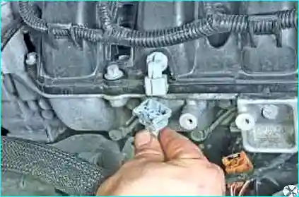
Fig. 14. Disconnect the connector from the sensor
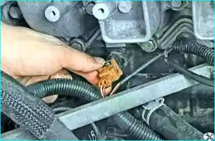
Fig. 15. Release the knock sensor wiring connector clip. Disconnect the connector from the sensor
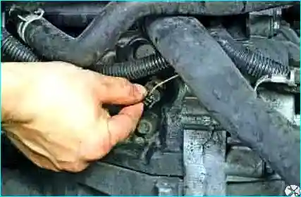
Fig. 16. Release the oil pressure sensor wiring connector clip
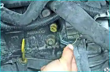
Fig. 17. Disconnect the connector from the sensor
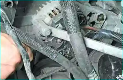
Fig. 18. Unscrew the alternator cable nut
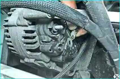
Fig. 19. Disconnect the alternator cable from the terminal
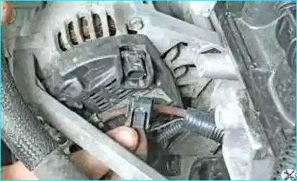
Fig. 20. Release the wiring harness connector clip. Disconnect the connector from the alternator
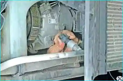
Fig. 21. Release the air conditioning system pressure sensor wiring connector clip. Disconnect the connector from the sensor
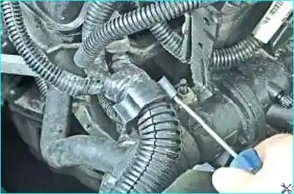
Fig. 22. Prise the wiring clamp. Fold back the clamp and move the wiring aside
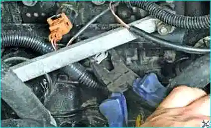
Fig. 23. Compress the bent tabs of the heater return hose clip
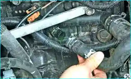
Fig. 24. Disconnect the cooling system connection
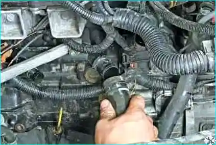
Fig. 25. Disconnect the radiator return pipe from the cooling system connection
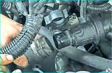
Fig. 26. Disconnect the radiator supply pipe
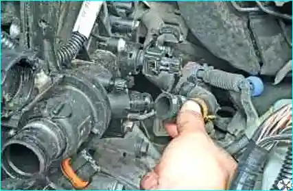
Fig. 27. Disconnect the heater supply hose from the water distributor
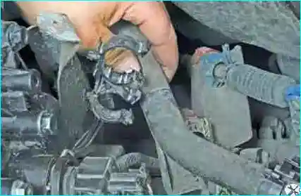
Fig. 28. Disconnect the heater hoses from the brackets
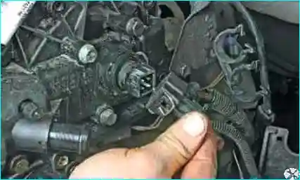
Fig. 29. Release the coolant temperature sensor wiring connector clip. Disconnect the connector from the sensor
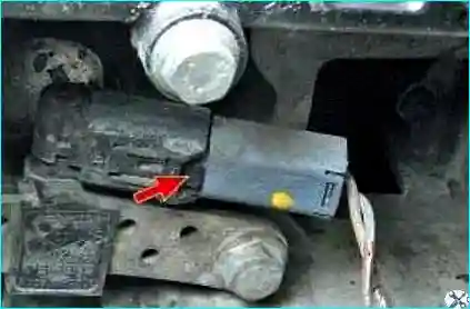
Fig. 30. Release the clip and disconnect the wiring connector from the crankshaft position sensor
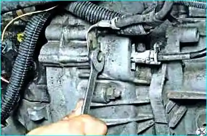
Fig. 31. Unscrew the earth cable bolt
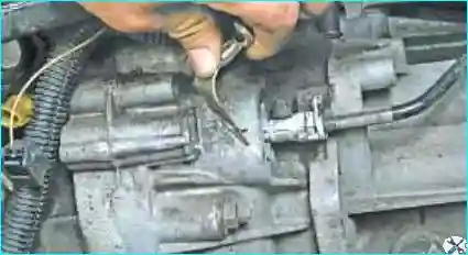
Fig. 32. Disconnect the earth cable from the gearbox housing
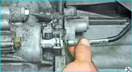
Fig. 33. Release the clip and disconnect the pipe from the clutch slave cylinder
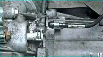
Fig. 34. Cap the pipe with the slave cylinder bleed connector cap
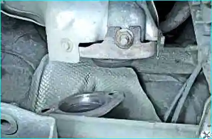
Fig. 35. Disconnect the front pipe from the exhaust manifold
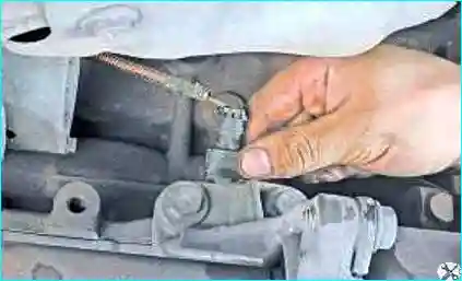
Fig. 36. Release the oil level sensor wiring connector clip. Disconnect the connector from the sensor
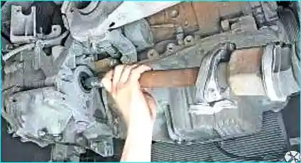
Fig. 37. Remove the front drive shafts
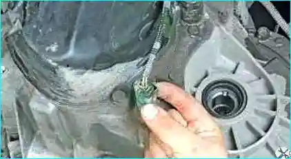
Fig. 38. Release the reverse light switch wiring connector clip. Disconnect the connector from the sensor
Release the upstream oxygen sensor wiring connector clip.
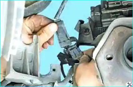
Fig. 39. Separate the connectors
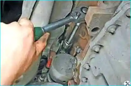
Fig. 40. Unscrew the starter earth cable nut
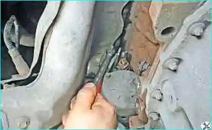
Fig. 41. Unscrew the starter power cable nut
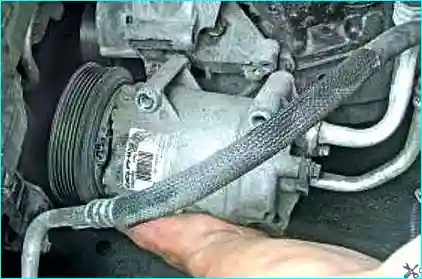
Fig. 42. Remove the air conditioning compressor without disconnecting the pipes, and secure it
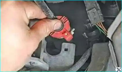
Fig. 43. Disconnect the gearbox control cables from the selector levers and remove them from the bracket
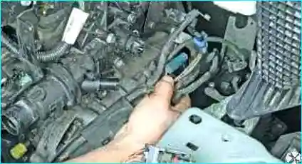
Fig. 44. Move the wiring harness aside
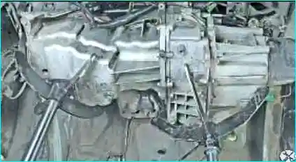
Fig. 45. Place supports under the powertrain
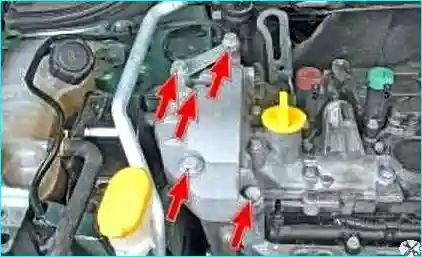
Fig. 46. Unscrew the five bolts of the right powertrain mount
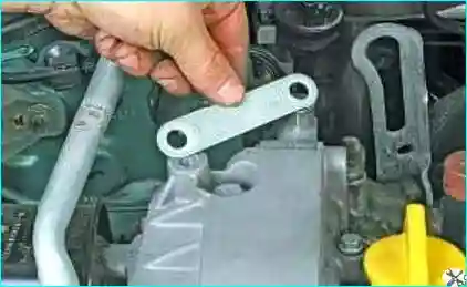
Fig. 47. Remove the mount bracket
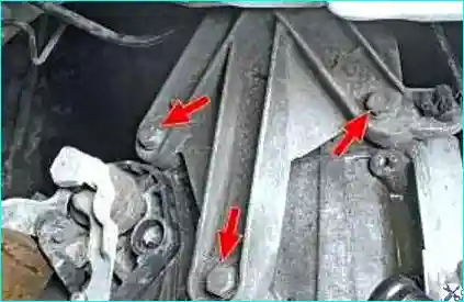
Fig. 48. Unscrew the three bolts securing the mount to the gearbox housing
Check once more that all wiring, hoses and auxiliary components are disconnected from the engine.
Lower the engine on its mounts, supporting it to prevent it from falling.
If it is not possible to lower the engine on its mounts, raise the front of the vehicle (on the lift) high enough to remove the powertrain from under the vehicle, and place secure supports under the body.
Install the engine, as well as all removed assemblies and components, in the reverse order of removal, taking note of the following:
- before installing the powertrain, clean the threaded holes of its mountings with a tap to remove rust;
- replace the front pipe gasket with a new one;
- when connecting wiring and pipes, carefully ensure they are correctly routed in the engine bay, avoiding contact with hot or moving parts of the powertrain.
Tighten to the specified torque:
- the upper front body panel bolts (21 N·m);
- the lower front body panel bolts (44 N·m);
- the front subframe retaining bolt (105 N·m);
- the rear subframe retaining bolt (21 N·m);
- the wheel bolts (110 N·m).
Top up the brake fluid reservoir.
Bleed the clutch hydraulic system.
Fill the gearbox with oil.
Fill the engine with oil.
Fill the cooling system with coolant.
Recharge the air conditioning circuit with refrigerant using a recovery station.
Securely fasten the brake hose and the ABS speed sensor wiring.
Do not twist the brake hose.
Connect the battery.
Bleed the cooling system.
Tighten the battery cover retaining bolts to the specified torque (4 N·m).


