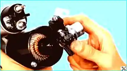
For this job you will need the following tools: 10 mm and 13 mm spanners, flat-blade screwdriver, multimeter.
The removal of the starter motor is covered in the article – Starter replacement Renault-Megane-2.
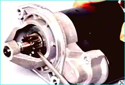
Starter check
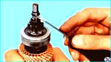
To check the starter drive, rotate the drive pinion with a screwdriver.
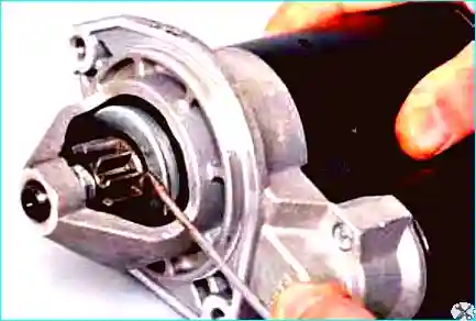
The pinion should rotate in one direction with the drive shaft, and in the other direction on the drive shaft.
Move the drive pinion along the shaft with a screwdriver.
The pinion should move freely along the shaft.
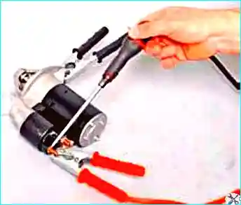
Check the starter itself: connect the battery positive terminal to the upper contact bolt of the solenoid relay, and the negative terminal to the starter housing.
Using a screwdriver, bridge the upper contact bolt and the solenoid relay control terminal.
The drive pinion should extend and the starter should engage.
If this does not happen, check the solenoid relay and the starter.
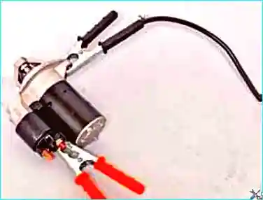
To check the starter motor, connect the battery positive terminal to the lower contact bolt of the solenoid relay, and the negative terminal to the starter housing.
The starter motor shaft should start to rotate.
If this does not happen, the starter motor is faulty.
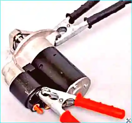
To check the solenoid relay, connect the battery positive terminal to the solenoid relay control terminal, and the negative terminal to the starter housing.
The drive pinion should extend.
If this does not happen, the solenoid relay is faulty.
Starter disassembly
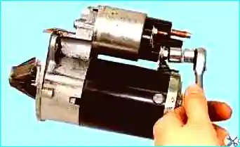
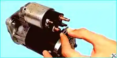
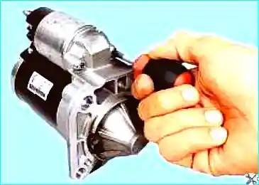
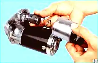
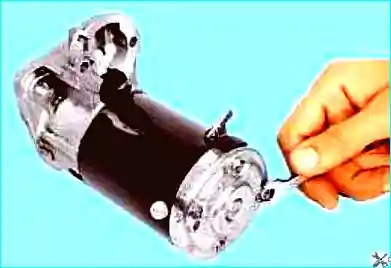
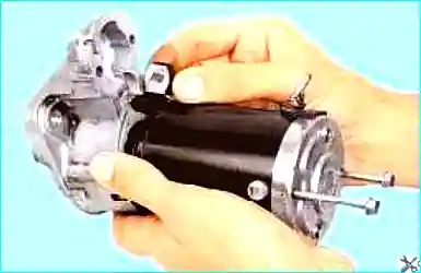
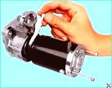
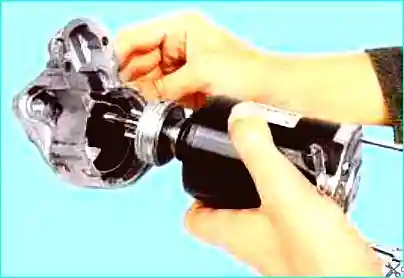
Remove the two screws securing the cover on the commutator side.
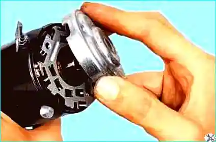
Remove the cover.
Remove the armature complete with brush holder from the stator.
Remove the brush holder from the armature.

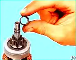
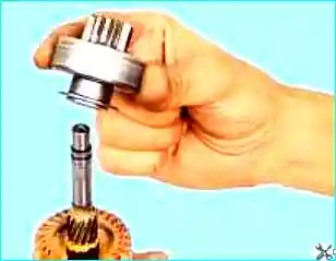
Inspect the brushes in the brush holder. The brushes should move freely in the brush holder.
The brush height should be at least 7 mm.
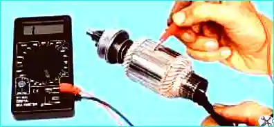
Check the insulated holders for short circuits using an ohmmeter.
The splines and journals of the armature shaft must not show any damage (burrs or scoring).
The armature commutator must not show any signs of burning.
Remove minor burning with a cloth soaked in petrol and fine-grit sandpaper.
Check the armature winding for short circuits using an ohmmeter.
The resistance should tend towards infinity.
Check that the solenoid relay armature moves freely and that the contact bolts are closed by the contact plate (using an ohmmeter).
Check the drive.
The drive pinion teeth should not show significant wear.
The pinion should rotate freely relative to the clutch hub in the direction of armature rotation and should not rotate in the opposite direction.
If the pinion teeth are worn or damaged, or if the pinion rotates in both directions, replace the drive.
The starter drive lever must not show any cracks or signs of significant wear on the fork grooves.
Assemble the starter in the reverse order of disassembly, taking the following points into account.
The drive clutch does not need to be lubricated during operation.
Clean the clutch of dirt.
Do not use any cleaning agents for the drive that may wash out the lubricant contained in the clutch.
Lubricate the splined surface of the armature shaft with silicone-based grease.
Lubricate the bearings (bushes) in the starter covers with engine oil.
Use circlip pliers to install the stop ring.
Before installing the solenoid relay, apply a thin layer of silicone sealant to the surface of the relay that contacts the starter cover on the drive side.