Renault/Dacia Sandero car starter four-pole, four-brush DC motor with permanent magnet excitation, combined with an electromagnetic two-winding traction relay
The covers and the stator housing are tightened with two bolts.
Permanent magnets are fixed in the stator housing.
The rotation from the armature shaft of the electric motor is transmitted to the drive gear through the freewheel.
When the key in the ignition switch is turned to position “D” (engine start), the voltage from the battery is applied to the retracting and holding windings of the traction relay, as a result, the drive lever moves and the starter gear engages with the toothed rim of the engine flywheel.
At the same time, the armature of the traction relay closes the power contacts (at this moment, the retractor winding is turned off) and voltage is supplied to the starter motor from the battery.
The starter armature rotates the engine crankshaft through the freewheel.
After starting the engine, when the speed of the gear exceeds the speed of the starter shaft, the freewheel will unlock and slip, protecting the starter from high speed and damage.
Possible starter malfunctions and solutions:
- Reason
Remedy
There is a loud noise when the starter armature is rotating:
- Loose starter mount
Tighten the starter mounting bolts
- The teeth of the starter drive gear or the engine flywheel ring are damaged
Repair the starter, replace the engine flywheel
- Faulty starter
Repair the starter
Starter does not turn on:
- Faulty battery
Check the battery
- Oxidation of battery terminals and wire ends
Clean, secure and lubricate wire lugs and terminals
- Violation of contacts in the connections, breakage of wires in the power supply and starter control circuits
Check, clean, tighten or replace contact connections in chains
- Violation of the ignition switch
Replace the contact group of the ignition switch
- Faulty starter
Repair or replace the starter
The traction relay turns on, but the starter armature does not rotate or rotates too slowly:
- Very low battery
Charge or replace the battery
- Oxidation of battery terminals and wire ends
Clean, fasten wire ends
- Faulty ignition switch (lock)
Replace the contact group of the ignition switch
Starter engages but gear does not engage:
- Nicks on the teeth of the drive gear or flywheel rim
Remove nicks or replace flywheel or starter drive
The starter does not turn on after starting the engine:
- Key stuck in the ignition in the "D" position
Repair or replace the ignition switch
- Closing the contacts of the ignition switch
Replace the ignition switch
- Faulty starter
Repair or replace the starter
Removing the starter
Disconnect the negative battery terminal
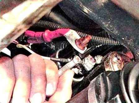
Unscrew the nut securing the control wire and disconnect the wire from the traction relay
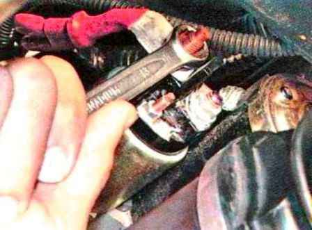
Unscrew the power cable nut
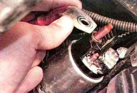
Remove the wire from the contact bolt of the traction relay
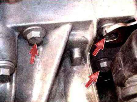
Unscrew the three starter mounting bolts
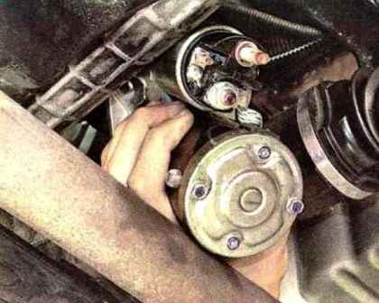
Remove the starter
Install the starter in reverse order
Starter repair
Before disassembling the starter, you need to check its serviceability.
Using a screwdriver, we check the ease of movement of the shaft drive freewheel
The drive gear should turn easily relative to The clutch hub must be aligned in the direction of rotation of the armature and must not rotate in the opposite direction.
We connect the negative terminal of the battery with the starter housing, and the positive terminal with the output of the control wire of the traction relay.
If the traction relay is working properly, a click will be heard and the drive clutch will extend. Otherwise, the traction relay must be replaced.
Disconnect the wire from the control output of the traction relay and connect it to the lower contact bolt of the traction relay.
The starter armature should begin to turn.
Otherwise, the starter needs to be repaired.
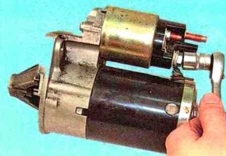
Unscrew the nut on the lower contact bolt
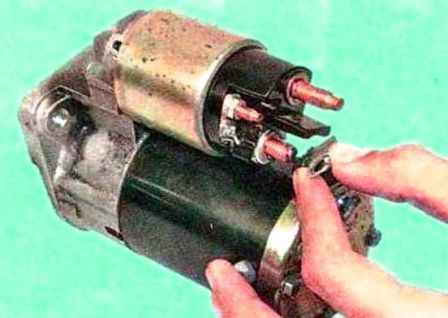
Disconnect the bus from the contact bolt of the traction relay
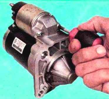
We unscrew the three screws securing the traction relay to the starter cover from the drive side
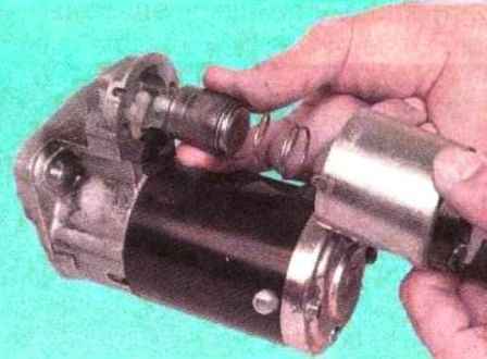
Remove the traction relay
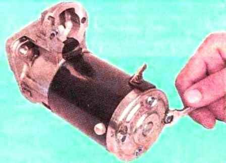
We unscrew the two bolts securing the cover on the drive side
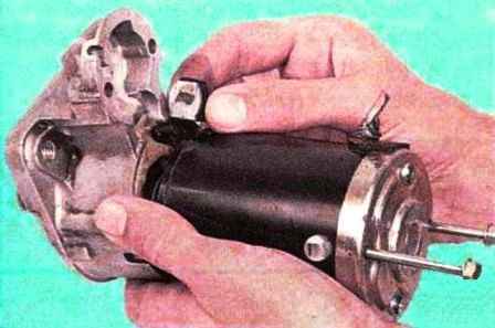
Disconnect the starter cover and housing, remove the lever support along with the rubber spacer
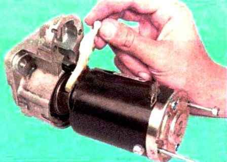
And the drive lever
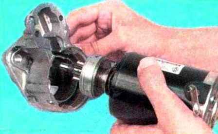
Remove the drive side cover
We unscrew the two screws securing the cover on the collector side
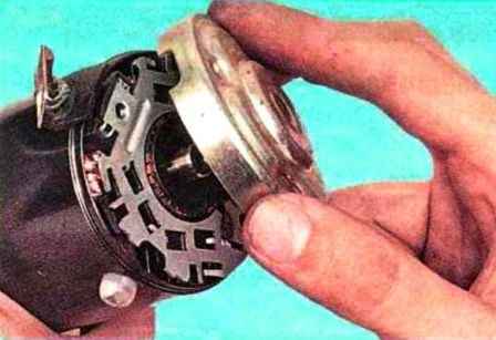
Remove the cover
We remove the anchor assembly with the brush holder from the starter
Remove the brush holder from the anchor
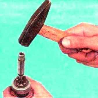
We move the restrictive ring along the armature shaft using a suitable mandrel
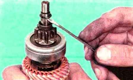
Pry off with a screwdriver and remove the retaining ring
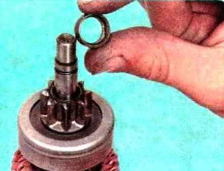
Remove the restrictive ring from the armature shaft
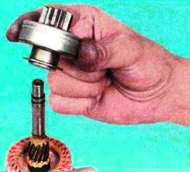
Remove the drive (bendix)
Detection of starter parts
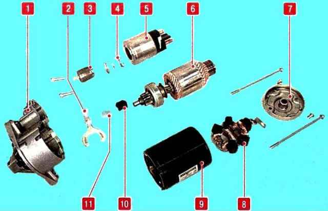
Inspecting the brush holder. Checking the height of the brushes.
If the height of the brushes is less than 7 mm, replace the brush holder assembly.
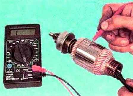
Check the armature winding for a short circuit using an ohmmeter.
Resistance should tend to infinity.
The splines and trunnions of the armature shaft must not be damaged.
The collector must not show signs of burning.
Insignificant burns are removed with a rag soaked in gasoline and fine emery cloth.
We check whether the armature of the starter traction relay moves easily, whether the contact bolts are closed with a contact plate.
Checking the drive. The teeth of the drive gear should not be heavily clogged.
The gear should turn easily relative to the clutch hub in the direction of rotation of the armature and should not turn in the opposite direction.
The starter drive lever must not show cracks or significant wear on the fork grooves.
Assemble the starter in reverse order
Lubricate the splined surface of the shaft with silicon-containing grease
Lubricate the bearings (bushings) in the starter covers with engine oil
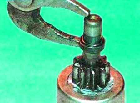
To install the restrictive ring, you can use sliding pliers
Before installing the traction relay, apply a thin layer of sealant to the surface of the relay in contact with the starter cover on the drive side.
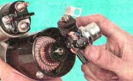
Before installing the brush holder on the anchor, spread the brushes and fix them with a suitable mandrel.


