

Important warnings and general requirements
Do not reuse: gaskets, O-rings, oil seals — replace them with new ones.
For lubrication and retention of components, use exclusively:
- blue petrolatum;
- white petroleum jelly.
Caution: Do not use other types of grease (e.g. lithium or molybdenum-based) unless otherwise specified, as they may damage rubber seals and impair hydraulic operation.
- Before installing friction elements (discs, brakes), lubricate them with automatic transmission fluid (ATF). Soak friction discs in ATF for at least 2 hours.
- Do not apply sealant/adhesive to gaskets.
- When replacing bushes, install the assembly as a complete unit.
- During assembly, do not use fabric gloves or rags. Permitted: nylon cloth, paper towels.
- Replace the working fluid (ATF) in the heat exchanger circuit.
Step-by-step assembly
1. Installation of the intermediate drive gear

- use guide MD998412;
- tighten the bolts to 34 ± 2 N·m.

2. Installation of the brake and return elements
Install:
- the low/reverse engagement brake;
- the return spring;
- the spring retainer.
3. Replacement of the one-way clutch seal ring
Install a new seal ring in the groove of the one-way clutch inner ring.

4. Installation of the one-way clutch inner ring
Install the one-way clutch inner ring:
- refer to the identification marks;
- align the marks along line A‑A (see figure);
- use the tools:
- spring remover screw (MD998924);
- spring compressor (MD998903);
- press down on the ring and install the snap ring.

5. Installation of the piston spring ring
Install the spring ring on the low/reverse engagement brake piston.

6. Installation of the brake disc pack
Install the brake disc pack:
- 4 friction discs;
- 3 steel discs;
- snap ring.
Do not install the pressure disc at this stage.
7–8. Installation of the special tool and reaction plate
- Install the special tool on the brake disc pack.
- Install:
- the reaction plate;
- the snap ring (removed during disassembly).
9. Checking the reaction plate axial clearance
Check the reaction plate axial clearance:

- lift the clearance measuring plate (MB991631);
- permissible clearance: 0–0.16 mm;
- if necessary, replace the snap ring (see step 10).
10. Installation of the auxiliary brake discs
Install:
- 2 friction discs;
- 1 auxiliary brake steel disc.
Do not install the pressure disc at this stage.

11–12. Installation of the measuring plate and piston
- Install the clearance measuring plate (MB991631).
- Install:
- the return spring;
- the auxiliary brake piston;
- the snap ring.


13. Selecting the pressure disc (auxiliary brake)
Measure the plate travel (MB991631). Select the pressure disc according to the table (permissible clearance: 0.49–0.95 mm).
| Plate travel, mm | Pressure disc thickness, mm | Identification mark |
|---|---|---|
| 0.3–0.5 | 1.6 | L |
| 0.5–0.7 | 1.8 | 1 |
| 0.7–0.9 | 2.0 | 0 |
| 0.9–1.1 | 2.2 | 2 |
| 1.1–1.3 | 2.4 | 4 |
| 1.3–1.5 | 2.6 | 6 |
14–15. Measuring the low/reverse brake clearance
- Turn the transmission upside down.
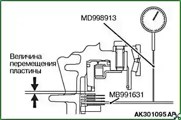
- Measure the plate travel (MB991631) using a dial indicator and extension (MD998913).
- Select the pressure disc according to the table (permissible brake clearance: 1.05–1.51 mm).
| Plate travel, mm | Pressure disc thickness, mm | Identification mark |
|---|---|---|
| 0.7–0.9 | 1.6 | L |
| 0.9–1.1 | 1.8 | 1 |
| 1.1–1.3 | 2.0 | 0 |
| 1.3–1.5 | 2.2 | 2 |
| 1.5–1.7 | 2.4 | 4 |
| 1.7–1.9 | 2.6 | 6 |
| 1.9–2.1 | 2.8 | 8 |
| 2.1–2.3 | 3.0 | D |
16–17. Removing elements and installing the snap ring
- Remove the elements installed in steps 7–17.
- Install the snap ring in the groove of the output shaft bore in the transmission case.

18–20. Output shaft bearing preload
- Install the adjusting ring (the thinnest, 1.88 mm) for the output shaft bearing preload.
- Install the output shaft bearing outer race:
- use drift (MB990930) and handle (MB990938);
- do not reuse the separator mounting bolts (they had sealant on them).

Tighten the separator bolts to 29 ± 2 N·m.

21–22. Installing the bearing and tightening the lock nut
- Install the tapered roller bearing on the output shaft:
- use tool MD998350;
- the lock nut has a left-hand thread.

Tighten the lock nut:
- apply ATF to the new nut;
- use a socket (MB990607) and a special socket (MB991625);
- tighten to 170 ± 10 N·m, then loosen by 1 turn and retighten to the same torque.

23–27. Measuring shaft travel and final tightening
- Measure the output shaft travel and record the result.
- Remove the elements installed in steps 20–24.
- Select and install the adjusting ring: thickness = shaft travel (step 25) + 1.88 mm + 0.01–0.09 mm (preload).
- Repeat steps 21–24.
- Stake the lock nut (in two places).

28–30. Installing the cap, carrier and sun gear
- Install the cap using drift (MB990931) and handle (MB990938).

Install the carrier assembly.

Install the reverse sun gear.

31–33. Assembling the low/reverse brake pack
- Install the spring ring on the low/reverse brake piston.

Install the pressure disc (selected in step 17), then:
- 4 friction discs;
- 3 brake steel discs.

Install the snap ring.

34–36. Installing the reaction plate and discs
- Install the reaction plate.

- Install the snap ring (selected in step 11).

Install:
- 2 friction discs;
- 1 brake steel disc;
- the pressure disc (selected in step 15).

37–38. Installing the return spring and snap ring
- Install the return spring and auxiliary brake.

Install the snap ring.

39–42. Installing the thrust bearings and friction elements
- Install thrust bearing #5 (side down, as shown).

- Install the overdrive clutch hub and thrust bearing #6 into the reverse and overdrive clutch (side down).

- Install the reverse and overdrive clutch and thrust bearing #7.

43. Installing the rear bearing and seal rings
- Insert the input shaft rear bearing into the rear cover using handle MB990938.

Install four seal rings.
The continuation of the assembly is described in the article — Automatic transmission assembly — continued.


