Before inspecting the gearbox parts, thoroughly clean them, use a brush or scraper to remove all deposits and clean the holes and splines from possible contamination; then wash (kerosene, solvent, etc.) to remove and dissolve all oil residues.
Blow off the parts with a stream of compressed air and wipe them carefully.
Blow out the bearings especially thoroughly, directing the stream of compressed air so as not to cause rapid rotation of the rings.
Crankcase and covers
There should be no cracks in the crankcase, and no wear or damage on the surface of the bores for bearings, seals, etc.
There should be no damage on the mating surfaces with the clutch housing, rear and lower covers to prevent oil leakage.
Smooth out minor damage with a file.
If the parts are too damaged or worn, replace them with new ones.
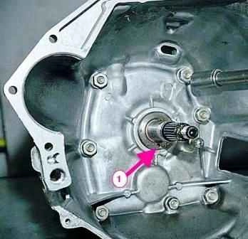
Check the condition of the front cover and make sure that the input shaft does not touch it when rotating.
If misalignment of the shaft and cover is detected, replace the damaged parts.
Check whether the oil drain hole in the cover is clogged (shown by the arrow in Figure 1).
Clean the drain plug.
Oil seals
Check the oil seals and make sure there is no damage, unacceptable wear or unevenness on the working edges.
The wear of the working edges of the seals in width is allowed to be no more than 1 mm.
If even a minor defect is detected, replace the seals with new ones.
Shafts
There must be no damage or excessive wear on the working surfaces and on the splines of the secondary shaft.
There must be no roughness or scoring on the rolling surfaces of the needles on the front end of the shaft.
Check the condition of the rolling surface of the needles in the bore of the primary shaft.
Inspect the intermediate shaft, which is not allowed to have chipping or excessive wear of the teeth.
The surface of the reverse gear axle must be completely smooth, without traces jamming.
The mounting clearance between the axle and the intermediate reverse gear bushing is 0.056-0.09 mm, the maximum allowable clearance is 0.15 mm.
Check the clearance by measuring the axle diameter and the gear bushing hole.
For new parts, the axle diameter is 19.079-19.094 mm, and the inner diameter of the pressed bushing is 20.05-20.07 mm.
Remove minor surface irregularities with fine sandpaper.
In case of major damage and deformation, replace the shafts with new ones.
Gears
The gears should not have any damage or excessive wear of the teeth.
Pay special attention to the condition of the tooth surface inclusions.
The contact patch of the gear teeth must be located over the entire surface, which must be smooth and without signs of wear.
Check the clearance in the engagement between the gear teeth, the installation value of which must be 0.10 mm; the wear limit is a clearance of 0.20 mm.
The installation clearance between the bushings and the gears of the 1st and 5th gears and between the secondary shaft and the gears of the 2nd and 3rd gears must be 0.05-0.10 mm; the wear limit is a clearance of 0.15 mm.
If wear exceeds the permissible limits, replace the gears with new ones.
Bearings
Ball or roller bearings must be in perfect condition. Their radial clearance should not exceed 0.05 mm.
Pressing the inner ring to the outer ring with your fingers, turn one of them in both directions, while rolling should be smooth.
No damage is allowed on the surface of the balls or rollers and the raceways of the rings.
Replace damaged bearings with new ones.
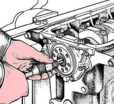
When replacing the front bearing of the primary shaft, use the A.40006 ejector (Figure 2); in this case, the flywheel can be left in place.
Rods and forks
Deformation of the gear shift forks is not allowed.
The rods must slide freely without significant clearance in the crankcase holes.
Check the condition of the rod locking crackers, springs and balls locks. Replace parts that show signs of seizing or wear with new ones.
Hubs, couplings and locking rings of synchronizers.
Check for signs of seizing on the coupling hubs, especially on their sliding surfaces.
Pay special attention to the condition of the ends of the teeth couplings.
Excessive wear of the surface of the locking rings is not allowed.
They must be replaced if their end rests against the synchronizer coupling.
Use a velvet file to remove any unevenness that prevents free sliding.
Replace parts that are worn beyond the permissible limits with new ones.
Pay special attention to the condition of the short teeth on the synchronizer hubs.
Replace parts with crushed ribs on the ends with new ones.
Gearbox assembly technology
Assemble the gearbox in the reverse order of disassembly.
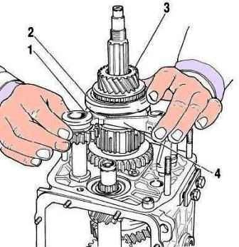
Removing the reverse intermediate gear, fifth gear assembly with synchronizer and fork: 1 - reverse intermediate gear: 2 - fifth gear engagement clutch: 3 - fifth gear and reverse gear: 4 - fifth gear and reverse gear fork
Please note that:
- - the reverse intermediate gear axle is secured before installing the shafts in the gearbox housing with a torque of 78 Nm (7.8 kgfm);
- - before installing the engagement fork rod fifth gear and reverse into the crankcase, install a spacer sleeve on it;
- - the inner bearing ring is pressed onto the fifth gear and reverse gear block, and the outer one is pressed into the rear cover socket;
- - the secondary shaft rear bearing is pressed onto the shaft to facilitate installation of the rear cover;
- - install intermediate gear 1 (see Fig. 3) of reverse, gear 3 and fork 4 simultaneously;
- - tighten the gear block mounting bolt to a torque of 78 Nm (7.8 kgfm);
- - coat the working surface of the oil seals with Litol-24 grease before installation;
- - use mandrels 41.7853.4028, 41.7853.4032, when installing oil seals and bearings, 41.7853.4039;
- - when assembling the gear selection mechanism, apply Litol-21 or LSC-15 grease to the surfaces of the gear selection lever that contact the ball joint and the tie rod joint housing.
Also apply grease to the inner surface of the spherical washer of the ball joint;
- - when assembling the gear shift control drive, apply LSC-15 grease to the inner surface of the ball joint housing;
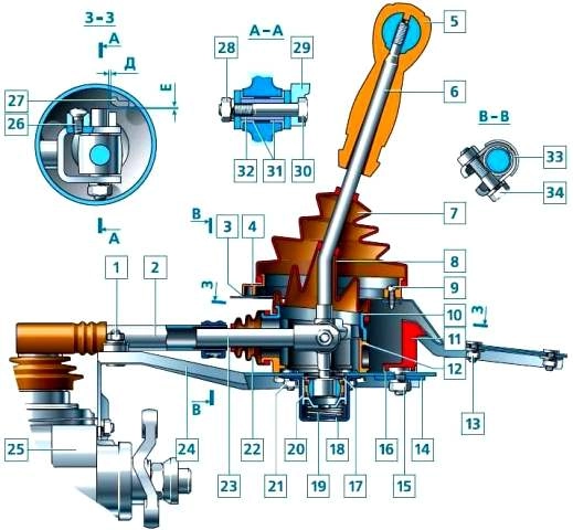
Gear shift mechanism control drive: 1 - support plate fastening nut; 2 - gearbox control drive rod; 3 - hatch cover gasket; 4 - gear shift lever hatch cover; 5 - gear shift lever handle; 6 - gear shift lever; 7 - gear shift lever boot; 8 - sealing boot; 9 - hatch cover fastening screw; 10 - gear shift lever upper housing; 11 - rear support; 12 - gear shift lever lower housing; 13 - rear support fastening nut; 14 - rear support washer; 15 - nut; 16 - spacer ring; 17 - retaining ring; 18 - ball joint housing; 19 - gear shift lever spring; 20 - ball joint slider; 21 - ball joint housing fastening nut; 22 - protective cover; 23 - tie rod end; 24 - support plate; 25 - gearbox; 26 - locking stop fastening screw; 27 - reverse gear locking pad; 28 - tie rod end fastening bolt nut; 29 - locking stop; 30 - tie rod end fastening bolt; 31 - bushing; 32 - spacer bushing; 33 - control drive tie rod clamp; 34 - clamp bolt
- - when installing the gearshift control drive, holding the gearshift lever and the support plate in a relative position determined by the dimensions (see Figure 4) D = (1.5 + 0.5) mm, E = (1 + 0.5) mm and W = (81.5 + 0.5) mm, tighten the clamp bolt of the control drive rod to a torque of 24.5 Nm (2.5 kgfm);
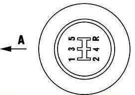
- - when installing the gear selector handle, ensure its position relative to the direction of vehicle movement as shown in view A (Fig. 5).


