


General information
The main repair operations of the five-speed gearbox are similar to the repair of the four-speed gearbox.
The dismantling and assembly of the four-speed gearbox are described in the article — “Dismantling and assembly of the gearbox”.
Design features of five-speed gearboxes
In five-speed gearboxes, since 1992, the washer on the secondary shaft is not installed and the configuration of the secondary shaft and the hub of the fifth gear synchroniser sleeve has been changed.
On the secondary shaft the diameter under the hub was 28 mm, it became 25 mm; the width of the seating part of the hub has become larger and the seating diameter has been reduced from 28 to 25 mm.
These parts are not interchangeable with those produced earlier, therefore when repairing a gearbox of “old” design the following rules are observed:
- if the washer is changed, the secondary shaft and the hub of “old” design are installed;
- if parts of the same name of “new” design are installed instead of the secondary shaft or the hub, they are changed as a set, that is, when replacing the hub the secondary shaft is also replaced and vice versa.
In this case the washer is not installed.
Dismantling the gearbox
Removing the flexible coupling and the gear lever
To facilitate the removal and subsequent installation of the flexible coupling, we wrap it tightly with adhesive tape.
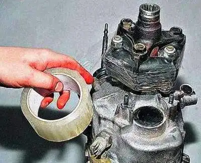
The flexible coupling can be clamped with a large band clamp.
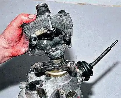
Having unscrewed three nuts with two 19 mm spanners and removed three bolts, we remove the coupling.
We remove the flexible coupling flange, the gearbox support, the speedometer drive.
With a 10 mm spanner, we unscrew the three nuts fastening the ball joint of the gear lever.
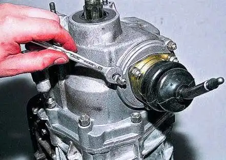
We remove the lever from the studs of the rear cover of the gearbox.
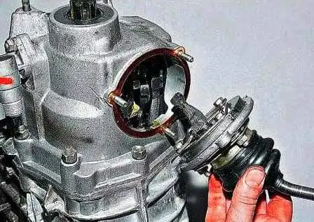
With a 27 mm spanner, we unscrew the reversing light switch and remove it.
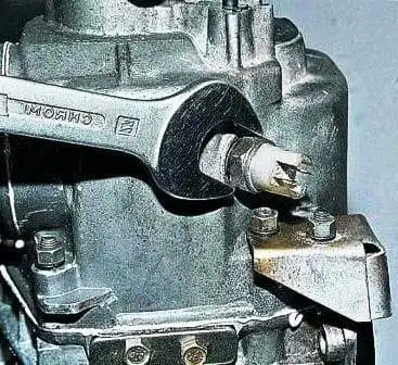
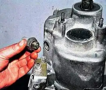
Removing the rear cover
We remove the lower cover of the gearbox (see Dismantling and assembly of the gearbox) and with a 13 mm spanner unscrew the nut fastening the rear cover to the gearbox crankcase.
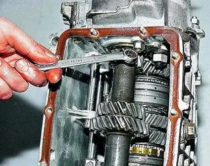
We unscrew the remaining nuts fastening the rear cover to the gearbox crankcase.
With a screwdriver, we press in the first and second gear engagement rod.
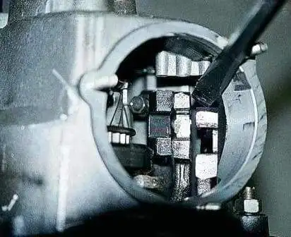
We remove the rear cover of the gearbox.
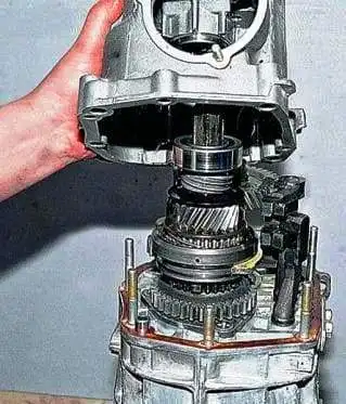
Removing the bearings and gears
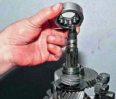
We remove the rear bearing of the secondary shaft and its inner race.
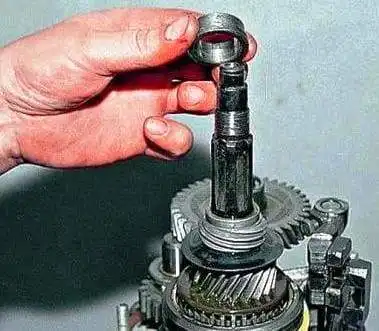
We remove the speedometer drive pinion with its retainer — a metal ball — and remove the oil deflector washer.
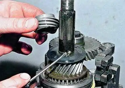
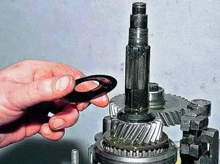
With a 10 mm spanner, we unscrew the bolt fastening the third and fourth gear engagement fork.
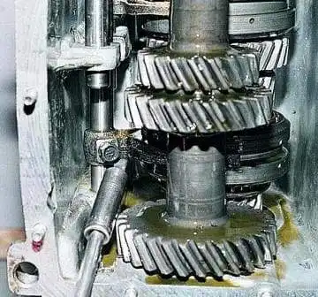
With a screwdriver, we engage the third gear.
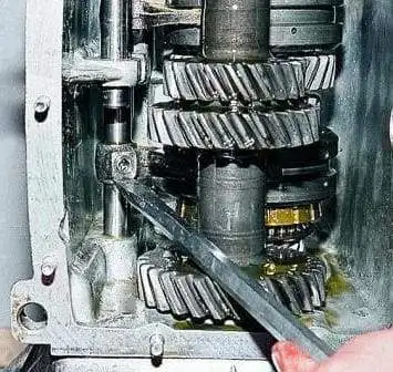
With a 17 mm spanner, we unscrew the bolt fastening the gear block.
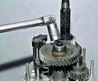
We remove the bolt fastening the gear block.
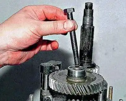
We extract the fifth gear and reverse gear block.
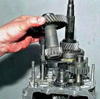
We remove the spacer washer.
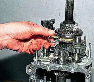
Removing the detents and gears
With a 13 mm spanner, we unscrew the two bolts fastening the detent cover and, having removed it, extract three springs and three detent balls.
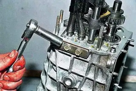
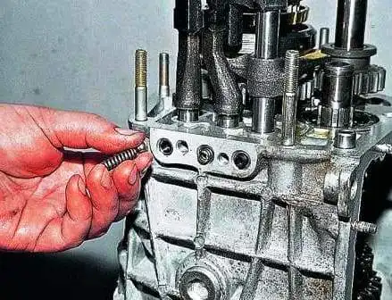
We remove the bush of the fifth gear.
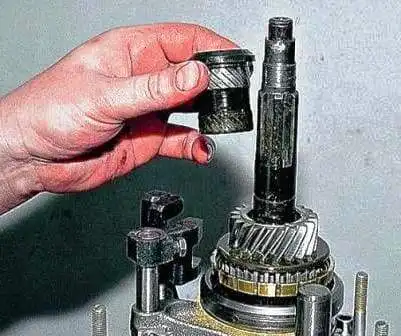
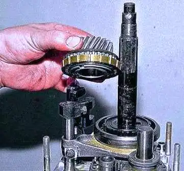
We remove the fifth gear assembly with the synchroniser.
Having raised the rod, we remove the V gear synchroniser sleeve.
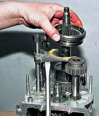
We remove the reverse intermediate gear.
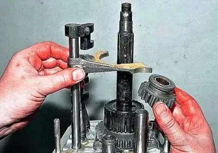
We remove the fifth and reverse gear engagement rod with the fork.
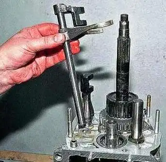
We remove the hub of the fifth gear synchroniser sleeve.
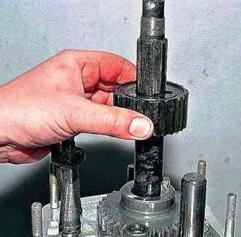
Further dismantling of the gearbox is carried out in the order described in the article — “Dismantling and assembly of the gearbox”.
Assembly
The assembly of the fifth stage, the reverse gear and the gear selection mechanism is carried out in the reverse order of dismantling, taking into account the following.
The reverse intermediate gear shaft is fastened before installing the shafts into the gearbox crankcase with a torque of 78 N·m (8 kgf·m).
Before installing the fifth and reverse gear engagement fork rod into the crankcase, we fit the spacer sleeve onto it.
The inner race of the bearing is pressed onto the fifth and reverse gear block, and the outer race — into the seat of the rear cover.
The rear bearing of the secondary shaft is pressed onto the shaft to facilitate installation of the rear cover.
The reverse intermediate gear, the fifth gear driven gear and its fork are installed simultaneously.
The gear block fastening bolt is tightened to a torque of 78 N·m (8 kgf·m).
Permissible dimensions of wearing parts of the gearbox
|
Mating parts |
Dimensions of mating parts |
Permissible clearance in the mating, mm |
|
|---|---|---|---|
|
Bore |
Shaft |
||
|
Primary shaft — front end of the secondary shaft plus two bearing rollers |
25.328 +0.021 |
19.3 -0.020-0.033 + 2(3-0.006) |
25.40 — bore 19.25 — shaft |
|
Synchroniser sleeve hub — secondary shaft |
38 +0.020-0.020 |
38 -0.030 |
0.05 |
|
III and II gear driven gears — secondary shaft |
43.5 +0.075+0.050 |
43.5 -0.025 |
0.15 |
|
I gear driven gear — driven gear bush |
43.5 +0.075+0.050 |
43.5 -0.025 |
0.15 |
|
I gear driven gear bush — secondary shaft |
30 +0.030+0.050 |
30.05 -0.016 |
0.016 |
|
Reverse gear driven gear — secondary shaft |
29.95 +0.030 |
29.95 -0.021 |
0.051 |
|
Reverse intermediate gear with bush — gear shaft |
20 +0.070+0.050 |
20 -0.006-0.021 |
0.15 |
Materials and tools used
- Adhesive tape or a large band clamp — to facilitate the removal and installation of the flexible coupling.
- 10, 13, 17, 19, 27 mm spanners — for unscrewing the nuts and bolts fastening the coupling, the support, the speedometer drive, the ball joint of the lever, the reversing light switch, the rear cover, the forks and the gear block.
- Screwdriver — for pressing in the first and second gear engagement rod and engaging the third gear.
- Pullers and mandrels — for removing and pressing on bearings, gears, synchronisers.
- Torque wrench — for tightening the intermediate gear shaft and the gear block bolt to 78 N·m (8 kgf·m).
- New gaskets, seals, detents (springs and balls), synchronisers, bearings — replacement parts in case of wear.
- Parts of “old” or “new” design (secondary shaft, hub of the fifth gear synchroniser sleeve, washer) — observe the interchangeability rules during repair.