The gearbox is mechanical with manual shifting, has five forward gears and one reverse gear, all forward gears are synchronized
The body parts of the gearbox — the clutch housing, the gearbox housing itself and the rear cover — are cast from aluminum alloy and pulled together with studs and nuts.
The joints are sealed with cardboard gaskets (sealant can be used during repairs).
The surface of the gearbox housing has ribs to improve heat dissipation.
The bottom of the housing is closed with a stamped steel cover with a gasket (fastened with studs).
The clutch housing is bolted to the engine cylinder block.

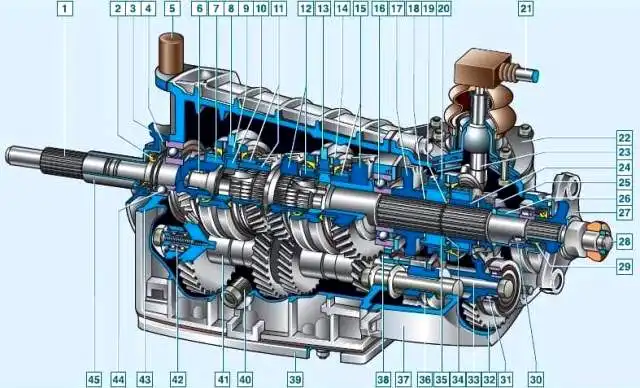
Gearbox: 1 - primary shaft; 2 - primary shaft oil seal; 3 - clutch housing; 4 - spring washer; 5 - breather; 6 - secondary shaft needle bearing; 7 - fourth gear synchronizer ring gear; 8 - third and fourth gear shift fork; 9 - third and fourth gear synchronizer sliding clutch; 10 - third and fourth gear synchronizer clutch hub; 11 - third gear synchronizer ring gear and pinion; 12 - second gear synchronizer ring gear and pinion; 13 - 1st and 2nd gear shift fork; 14 - 1st and 2nd gear synchronizer sleeve; 15 - 1st gear synchronizer pinion and toothed ring; 16 - secondary shaft intermediate bearing; 17 - reverse gear driven pinion; 18 - spring washer; 19 - retaining ring; 20 - 5th gear synchronizer sleeve; 21 - gearbox control drive rod; 22 - gear shift lever housing; 23 - gear shift lever; 24 - 5th gear driven pinion; 25 - oil deflector washer; 26 - spacer sleeve; 21 - elastic coupling flange; 28 - secondary shaft; 29 - secondary shaft oil seal; 30 - secondary shaft rear bearing; 31 - gear block bearing; 32 - 5th gear and reverse gear gear block; 33 - gear block mounting bolt; 34 - thrust washer; 35 - 5th gear synchronizer clutch hub; 36 - reverse intermediate gear; 37 - rear cover; 38 - intermediate shaft rear bearing; 39 - lower cover; 40 - filler plug; 41 - intermediate shaft; 42 - intermediate shaft front bearing; 43 - gearbox housing; 44 - primary shaft rear bearing; 45 - Clutch release bearing guide sleeve
To ensure alignment of the engine crankshaft and gearbox input shaft, the crankcase is centered on two bushings (grooves are made for them in the mounting holes of the block and crankcase).
The third support of the power unit is installed on the rear cover of the gearbox.
It is attached to the crossmember, and the last one is attached to the body floor (on welded bolts).
Gearbox gear ratios:
- - first gear 3.67
- - second gear 2.10
- - third gear 1.36
- - fourth gear 1.00
- - fifth gear 0.82
- - reverse 3.53
There is a filler (inspection) hole on the left side of the gearbox housing, and a drain hole in the lower cover of the housing.
The holes are closed with plugs with a conical thread.
There is a magnet in the drain plug.
It traps steel particles that get into the oil when parts wear out.
A breather is screwed into the upper part of the clutch housing.
It prevents the pressure in the gearbox from increasing when it heats up.
If the breather is faulty (the cap is jammed), a strong oil leak through the seals is possible.

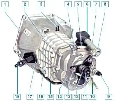
External view of the gearbox assembly with the clutch release drive mechanism: 1 - clutch housing; 2 - gearbox housing; 3 - breather; 4 - gearshift lever housing; 5 - flange; 6 - rod boot; 7 - drive rod; 8 - rod clamp; 9 - reverse light switch; 10 - intake pipe mounting bracket; 11 - centering sleeve; 12 - centering sleeve seal; 13 - elastic coupling flange; 14 - rear cover; 15 - lower cover; 16 - filler plug; 17 - clutch release fork boot; 18 - clutch release fork
There are three shafts in the gearbox: primary, secondary and intermediate.
The primary shaft rests on two ball bearings located in the rear end of the crankshaft and in the front wall of the gearbox housing (the latter takes the bulk of the load).
A bearing is installed in the rear end of the primary shaft and a needle bearing, which is the front support of the secondary shaft and ensures the alignment of the shafts.
The secondary shaft also rests on a ball bearing in the rear wall of the gearbox housing and a roller bearing in its rear cover.
The intermediate shaft rotates in two bearings:
the front one is a double-row ball bearing located in the front wall of the gearbox housing, the rear one is a roller bearing located in its rear wall.
The primary shaft has two toothed rims.
The helical rim, located closer to the front wall of the housing, is in constant engagement with the front gear of the intermediate shaft (thus, these shafts always rotate together).
The spur rim of the primary shaft is the rim of the synchronizer of the fourth gear (when it is engaged, the torque is transmitted directly from the primary shaft to the secondary, bypassing the intermediate, so this transmission is often called "direct").
The intermediate shaft is a block of four helical gears.
When any gear except IV is engaged, torque is transmitted to the secondary shaft through the intermediate shaft.
The gears of the intermediate shaft are arranged in the following order (from its front end): a gear of constant engagement with the primary shaft, gears of III, II and I gears.
A block of two gears is attached to the rear end of the shaft with a bolt: reverse (spur) and fifth gear (helical).
It additionally rests on a roller bearing in the rear cover of the gearbox.

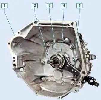
View of the gearbox from the input shaft side: 1 - clutch housing, 2 - input shaft; 3 - clutch release bearing guide sleeve; 4 - clutch release bearing; 5 - clutch release fork
The secondary shaft contains the driven gears of III, II, I gears, reverse and fifth gear (in order, counting from the front end of the shaft) and synchronizers.
The driven gears of the forward gears are in constant engagement with the corresponding gears of the intermediate shaft.
The gears of V, III and II gears rotate on hardened journals of the secondary shaft, the gear of the first gear - on the sleeve.
Involute splines are used to fix the driven gear of reverse and the hubs of the fifth gear synchronizer clutch on the secondary shaft.
A retaining ring is installed on the secondary shaft, located between the synchronizer hub and the driven gear of fifth gear.
Along with helical gears The gear rims of their synchronizers are made of forward gears - spur gears of a smaller diameter.
They are directed towards the corresponding synchronizer (III, I, V - forward, II - backward).
At the rear end of the secondary shaft, a flange of an elastic coupling is secured with a nut.
The synchronizer consists of a hub rigidly fixed to the secondary shaft, a sliding clutch, a retaining ring, a blocking ring and a spring with a washer.
The hubs of the synchronizers of III-IV and I-II gears enter with internal projections into grooves on the secondary shaft, and the hub of the synchronizer at the gear is held by the same key as the driven reverse gear gear.
On the outer surface of the hubs there are splines along which the sliding clutches move. The couplings have recesses into which the gearshift rod forks enter.
The inner rims of the locking rings are connected to the rims of the synchronizers of the corresponding gears and are pressed by springs towards the sliding couplings.

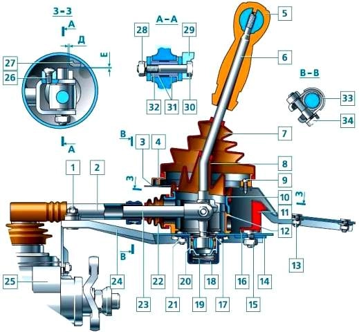
Gearshift mechanism control drive: 1 - support plate fastening nut; 2 - gearbox control drive rod; 3 - hatch cover gasket; 4 - gearshift lever hatch cover; 5 - Gear shift lever handle; 6 - Gear shift lever; 7 - Gear shift lever boot; 8 - Sealing boot; 9 - Hatch cover fastening screw; 10 - Gear shift lever upper housing; 11 - Rear support; 12 - Gear shift lever lower housing; 13 - Rear support fastening nut; 14 - Rear support washer; 15 - Nut; 16 - Spacer ring; 17 - Snap ring; 18 - Ball joint housing; 19 - Gear shift lever spring; 20 - Ball joint slider; 21 - Ball joint housing fastening nut; 22 - Protective boot; 23 - Tie rod end; 24 - Support plate; 25 - Gearbox; 26 - Locking stop fastening screw; 27 - Reverse locking lining; 28 - Tie rod end fastening bolt nut; 29 - locking stop; 30 - traction rod end mounting bolt; 31 - bushing; 32 - spacer bushing; 33 - control rod clamp; 34 - clamp bolt
The springs rest on the side surface of the driven gears through the washers.
The reverse gear does not have a synchronizer.
To engage it, you need to engage the intermediate reverse gear with the driven gear of the secondary shaft and the drive gear of the gear block.
The axis of the intermediate reverse gear is attached to the rear wall of the gearbox housing.
The gear shift mechanism consists of a guide plate with eight rectangular cutouts in the center, upper and lower washers, a gear shift lever and its housing.
These parts are pulled together with three bolts.
The gear selection mechanism is attached with three studs to the rear cover of the gearbox.
The neutral position of the lever between III and IV gears is set by two pairs spring-loaded guide strips installed in the grooves of the guide plate and acting on the lower end of the lever.
The gear shift drive consists of three rods connected to forks. The forward gear forks enter the grooves of the synchronizer sliding clutches, and the reverse gear fork enters the groove on the intermediate gear.
Accidental engagement of reverse gear instead of fifth gear is impossible due to the locking stop attached to the fork of the rod end and the locking lining fixed to the upper housing of the gear shift lever.
To engage reverse gear, you need to press the lever down - this causes the locking stop to drop below the locking lining.
The gearbox parts are lubricated by splash.
The primary and secondary shafts are sealed with oil seals.


