We remove the engine from the car, as described in the previous article
Remove the oil filter and the right arm of the power plant support
We fix the engine on the stand for the studs of the right support bracket (if the stand is available)
Remove the dipstick
Remove the fan impeller, drive belts, generator and starter
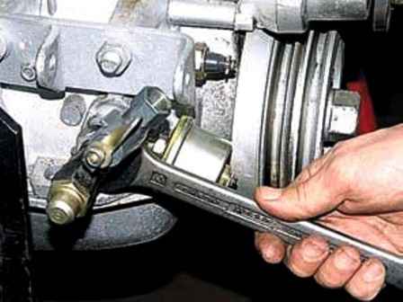
Weaken the fitting and turn it upside down
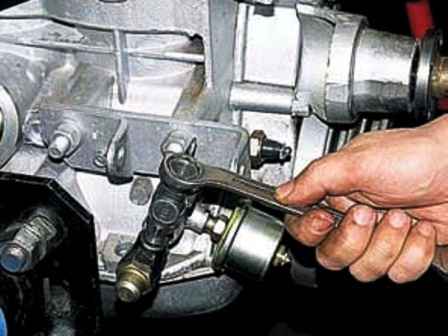
Using a 19 wrench, unscrew the oil cooler tap
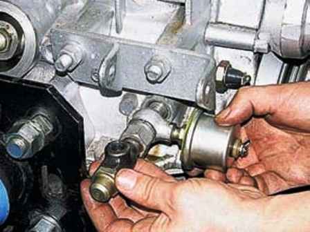
Finally unscrew the fitting with the valve and remove the oil pressure indicator sensor
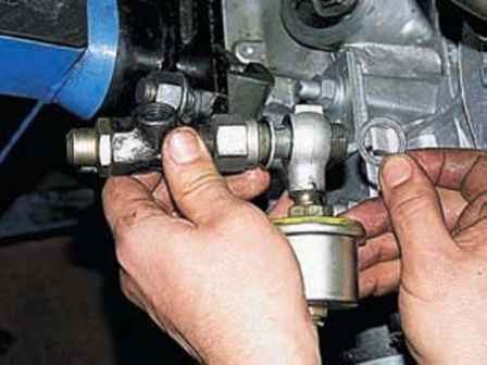
Sensor fitting sealed with two washers
Unscrew the emergency oil pressure sensor
Remove the fine fuel filter
Remove the fuel pump
Remove the distribution sensor together with the drive and high-voltage wires
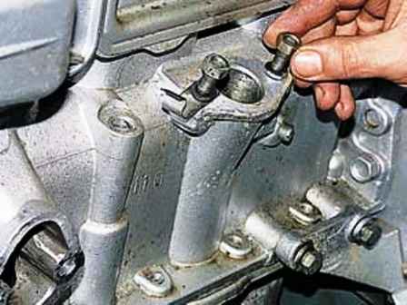
In order not to lose fasteners, after removing the parts, we bait them into place
Remove the starter
Remove the intake manifold and exhaust manifold, as described in the article "How to remove the intake and exhaust manifold of a UAZ-3151, -31512, -31514, -31519 car engine"
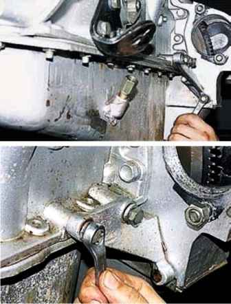
Using keys for 12 and 14, we unscrew two bolts securing the amplifier and remove it
Turn the engine upside down
Remove the clutch release fork
Remove the flywheel
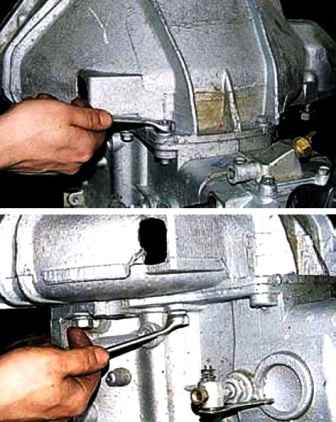
Using a 14 wrench, unscrew the two bolts of the upper mounting of the clutch housing and two middle bolts
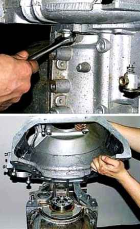
Using a 17 key, we unscrew the two bolts of the lower crankcase mount and remove the upper part of the crankcase
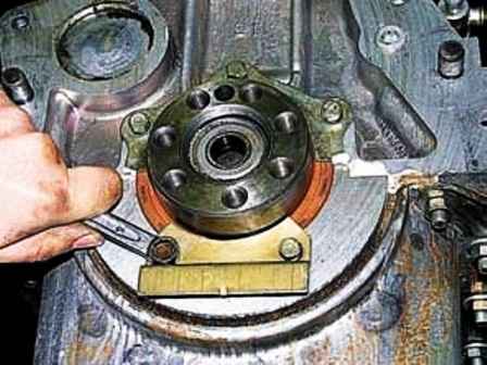
Using a wrench or a head, unscrew the two bolts of the lower and three bolts of the upper cuff mounting plates and remove the plates
Turn over the engine and remove the cylinder head, see the article "removing the cylinder head"
Turn the engine upside down
Remove the crankshaft pulley with the bushing
Remove the coolant pump
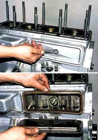
Using a 13 wrench, unscrew the nut and remove the cover of the pusher box and its gasket
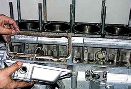
In the same way, remove the second cover (with oil separator)
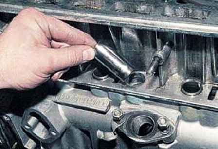
On a 2.5 liter engine, we take out eight valve lifters and number them
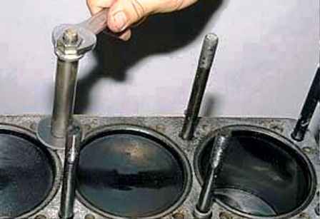
We fix the cylinder liners from falling out
Turn the engine upside down
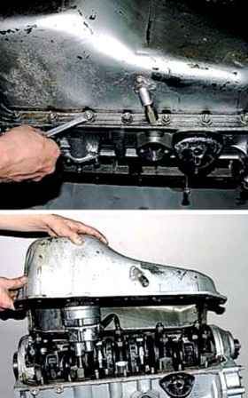
Using a 13 key, we unscrew the eighteen nuts securing the pallet
Curly washers are installed under the angle nuts
Removing the pallet
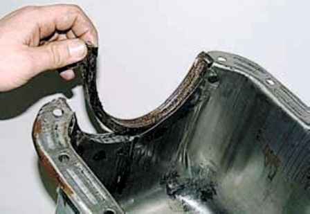
Remove the gaskets from the pallet
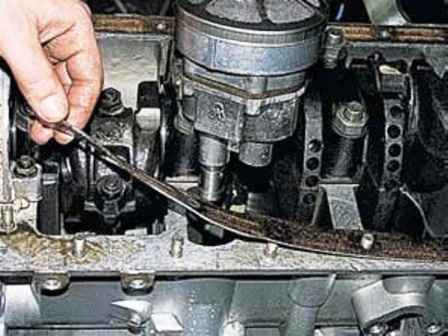
Remove the side parts of the pallet gasket from the block
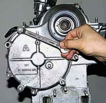
We unscrew the three remaining nuts securing the front cover of the cylinder block
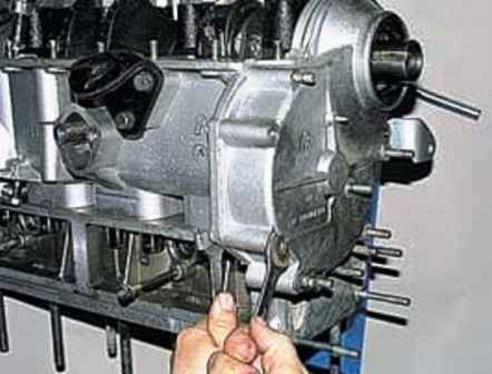
With keys 12 and 14, we unscrew the bolt with the nut for fastening the cover
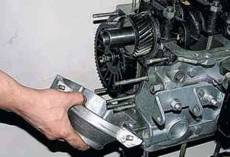
Remove the front cover
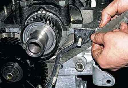
Remove the cover gasket by prying it with a knife
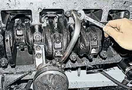
Using a 13 wrench, unscrew the two nuts securing the oil pump discharge pipe
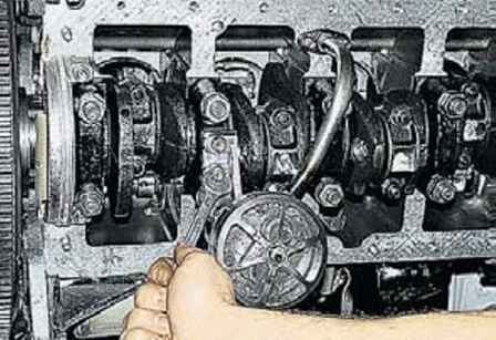
Using a 12 wrench, unscrew the two bolts securing the pump to the cover of the crankshaft main bearing
Remove the oil pump
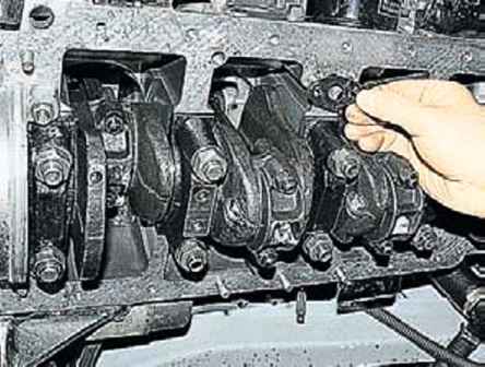
There is a gasket between the pipe and the block
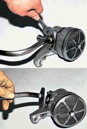
Using a 13 key, unscrew the two nuts securing the pipe to the pump and remove the pipe and gasket
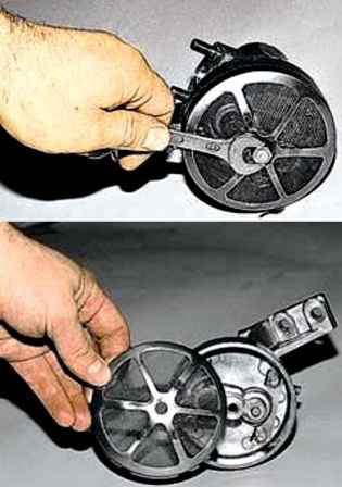
Using a 12 wrench, unscrew the bolt securing the oil intake grid and remove it
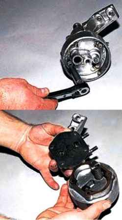
With a screwdriver, we bend the antennae of the locking plates and with a 10 head we unscrew the four bolts securing the pump cover
We take out the bolts and, having marked the relative position of the parts, remove the oil intake
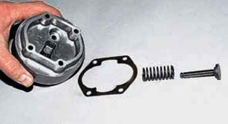
We remove the pressure reducing valve with a spring from the oil intake
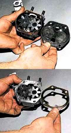
Remove the cover with shims from the pump housing
Assembling the pump, by filling its parts with engine oil and washing the oil intake screen with a solvent
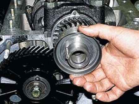
Remove the oil deflector of the front end of the crankshaft
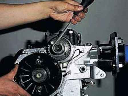
Turn the crankshaft so that the holes in the camshaft gear are opposite the heads of the bolts securing the camshaft thrust flange
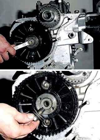
To replace the camshaft gear with a 17 key, unscrew the bolt securing the camshaft gear and remove it together with the washers
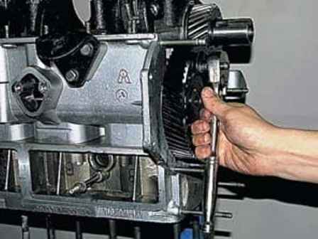
Head 12 through the hole in the gear, unscrew the two bolts securing the thrust flange
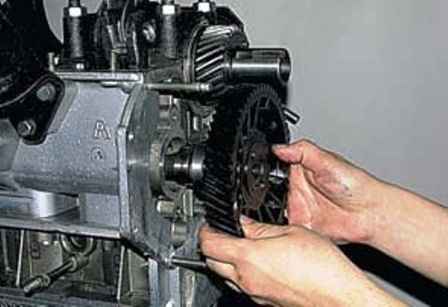
Remove the camshaft together with the gear
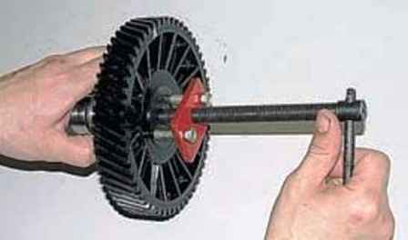
Using a puller, remove the gear from the camshaft and press a new one through the mandrel
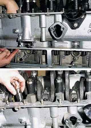
Pressing from below, we take out the pushers
Pushers are laid out in order or marked
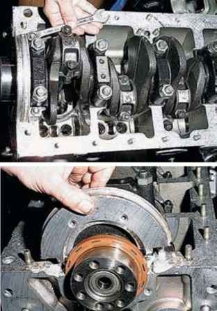
Using a 13 key, unscrew the two nuts and remove the cuff cover (the cover is planted on the sealant)
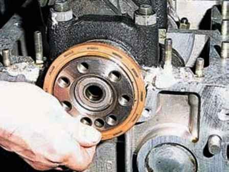
Remove the back cuff
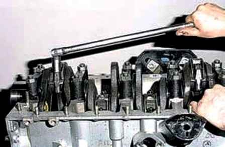
Using a 15 head, unscrew the connecting rod cap nuts
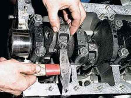
Tapping with a hammer on the sides of the cover, we pull it off the bolts
If necessary, the connecting rod bolts can be knocked out through a soft metal mandrel
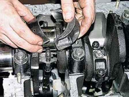
Remove the connecting rod cap along with the liner
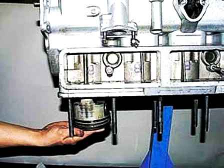
Remove the piston with the connecting rod from the cylinder block
In the same way, we take out the pistons of the remaining cylinders
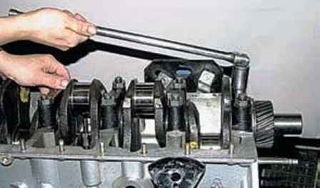
We unscrew the nuts of the main bearing caps with the help of a head for 22
Mark all lids
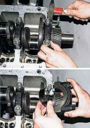
By tapping the root caps with a hammer, we remove them one by one along with the liners
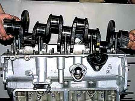
Removing the crankshaft
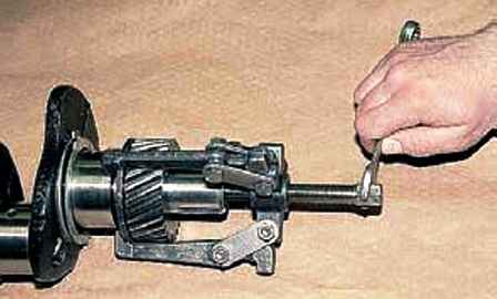
With a puller, we press the gear from the crankshaft together with the thrust washer
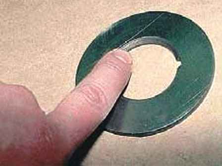
During assembly, we install the washer so that the chamfer of the hole faces the opposite side of the gear
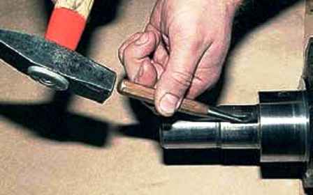
Knock out the gear key from the groove on the crankshaft
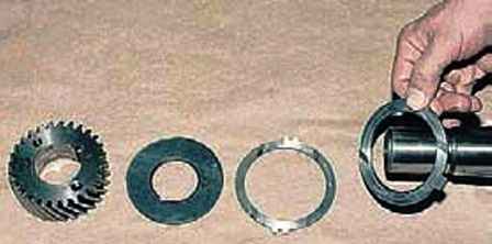
Remove the thrust washers limiting the axial movement of the crankshaft
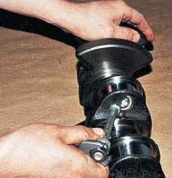
Grinding the crankshaft, if it is subject to grinding
After grinding with a 14 hexagon, unscrew the plugs
We clean the channels for the passage of oil in the crankshaft from deposits and abrasive residues
We wash the channels of the crankshaft with kerosene and blow with compressed air
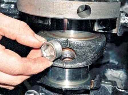
Installing the plugs of the oil channels
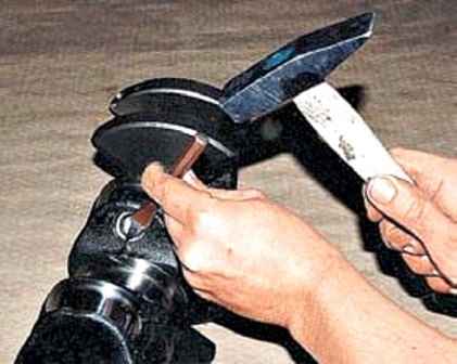
With the help of a beard, we sharpen the edges of the plugs
Further assembly of the crankshaft is carried out in reverse order


