We remove the elements of the rear suspension of the car for replacement or repair
Removing the anti-roll bar
We remove the anti-roll bar strut for replacement if play appears in its ball joints, damage to the protective covers of the hinges and when repairing other suspension elements.
We carry out work on a flat area, a viewing ditch or overpass.
Hang out the back of the car - both rear wheels, since when hanging only one wheel, the stabilizer is "stressed" and interferes with dismantling.
We securely fix the car on factory-made stands.
The work is shown on the left stabilizer strut, we remove the right strut in the same way.
Remove the wheel.
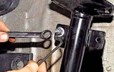
Using a 16 wrench, unscrew the nut securing the pin of the upper hinge of the stabilizer strut to the shock absorber strut bracket, holding the finger from turning with a 5 hexagon
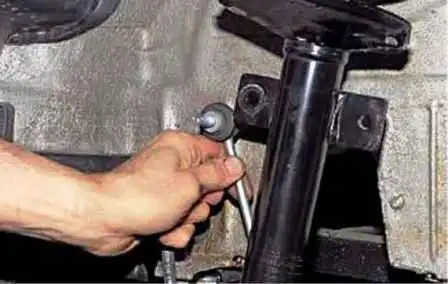
We remove the pin of the upper hinge of the stabilizer strut from the hole of the shock absorber strut bracket.
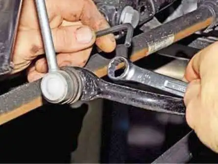
We also unscrew the nut that secures the pin of the lower hinge of the strut to the stabilizer bar
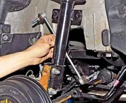
Remove the anti-roll bar
Install the anti-roll bar in reverse order.
Tightening torques for fasteners of the rear suspension of a 4x4 car:
- - nut of the upper mounting of the shock absorber strut to the body - 44 Nm;
- - nut for fastening the upper support of the shock absorber strut - 62 Nm;
- - nut of the shock strut bolt to the knuckle - 105 Nm;
- -bolt for fastening the bracket of the anti-roll bar cushion to the subframe - 25 Nm;
- - nut for attaching the ball joint pin of the anti-roll bar - 35 Nm;
- - nut of the bolt of fastening of the front / rear transverse lever to the subframe and knuckle - 125 Nm;
- - nut of the trailing arm bolt to the knuckle and body bracket - 125 Nm;
- - rear wheel bearing nut - 280 Nm.
Replacing the anti-roll bar pads, removing the bar
We replace the rubber pads of the anti-roll bar of the rear suspension if they break and swell the rubber, as well as if the pads are significantly worn, as a result of which there is a play in the connection of the parts.
We remove the stabilizer bar for replacement if it is mechanically damaged.
We install the car on a viewing ditch or lift
We hang out the rear of the car - both rear wheels, since when hanging only one wheel, the stabilizer is tense and interferes with dismantling.
We fix the car on stands.
Remove the wheel
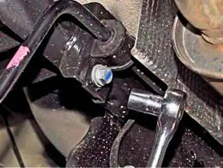
To replace the pillow with a head of 16, unscrew the bolt securing the stabilizer bar bracket to the subframe
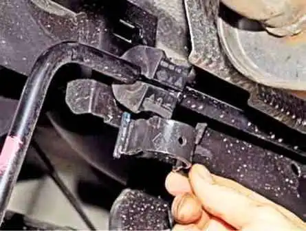
Remove the bracket
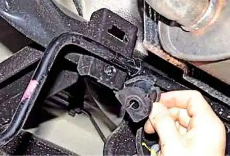
Remove the anti-roll bar cushion
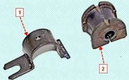
Install the pillow and stabilizer bracket in reverse order
To remove the stabilizer bar, disconnect the stabilizer struts from it, as described above, remove the stabilizer bar cushions
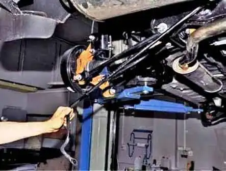
Remove the stabilizer bar
Install the stabilizer bar in reverse order.
Removing the shock strut and disassembling it
Remove the shock absorber strut to replace its elements.
We carry out work on a flat area, a viewing ditch or overpass.
We disassemble the shock absorber strut when it is necessary to replace its upper support, upper support bearing, spring, compression stroke buffer with a protective cover or telescopic strut (shock absorber).
If the telescoping strut or spring is defective, both struts or springs must be replaced so that the characteristics of the shock absorber struts on both sides of the vehicle are the same.
The work is shown on the example of the left shock strut.
Opening the tailgate, remove the curtain
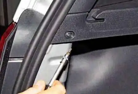
Using the Torx T-20 key, unscrew the self-tapping screw of the rear fastening of the left luggage compartment shelf
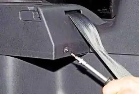
With the same tool, unscrew the self-tapping screw of the front fastening of the shelf
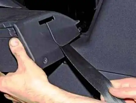
Move the shelf forward along the rear passenger's seat belt
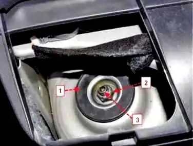
Shock strut mounting
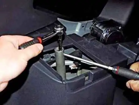
Using a 21mm tubular wrench, we loosen the nut that secures the shock strut rod to the body, holding the shock absorber rod from turning with a hexagon 6
Remove the wheel and securely fix the car on a factory-made stand.
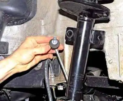
Disconnect the anti-roll bar from the shock strut bracket
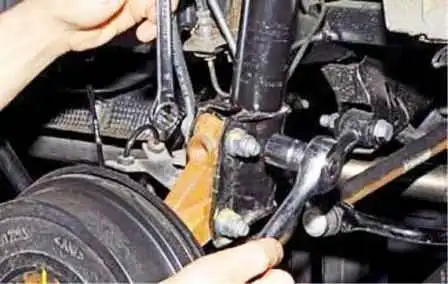
With a head of 18, we unscrew the nut of the bolt of the upper fastening of the shock strut to the knuckle of the rear suspension, holding the bolt with a key of 18.
We also unscrew the nut of the lower rack mounting bolt.
We take out the bolts or knock them out with a soft metal drift.
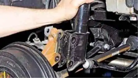
Remove the shock absorber from the fist.
Keeping the rack from falling, finally unscrew the nut of its upper fastening
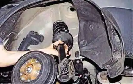
And remove the shock strut
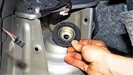
Remove the rubber-metal shock mount support washer
To disassemble the shock strut, clamp the shock strut bracket in a vise
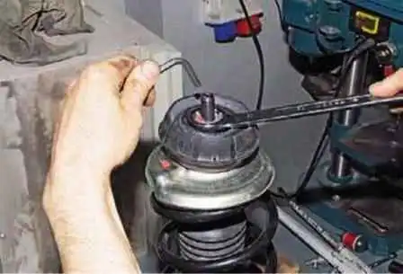
Using a 27 spanner wrench, unscrew the nut securing the upper support, holding the stem from turning with a hexagon 6
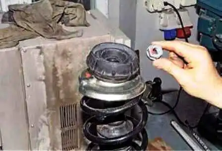
And remove the nut
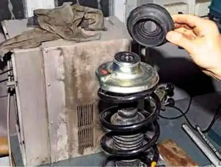
Remove the upper rubber support of the rack
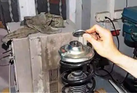
Removing the bearing of the upper support
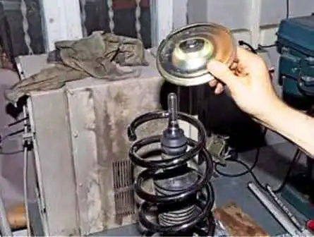
Remove the top spring cup
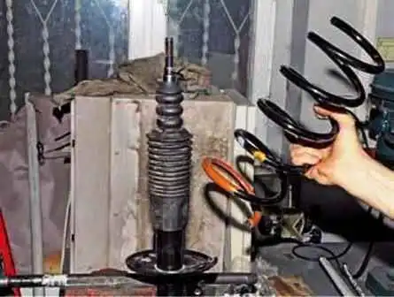
Remove the spring
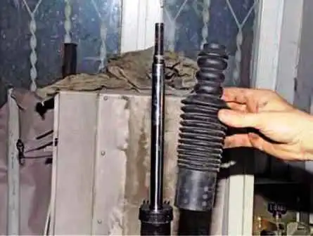
Remove the compression stroke buffer with the protective cover of the rod
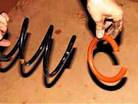
Remove the vibration-absorbing cover from the lower coil.
We assemble and install the shock strut in the reverse order.
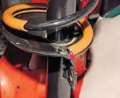
We install the spring so that its lower coil rests against the protrusion of the lower support cup of the spring welded to the body of the telescopic strut
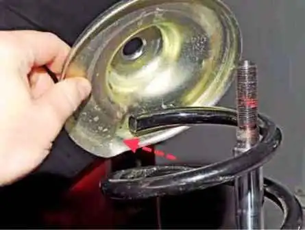
The upper coil should rest against the stamping of the upper spring support cup.
We tighten the nut of the strut to the body and the bolts of the strut to the fist with the moments indicated at the beginning of the article.
Removing the rear suspension arms
We remove the rear suspension arms if they are deformed, as well as if the silent blocks are heavily worn.
We install the car on a lift or a viewing ditch.
Remove the rear wheel from the side of the lever being replaced
Securely fix the car on the stand
Removing the rear transverse arm
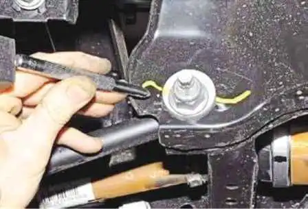
The rear suspension has adjustable toe angles, so we mark the position of the eccentric washer relative to the subframe with a center punch so that during subsequent assembly it would be possible to approximately maintain the wheel alignment angles.
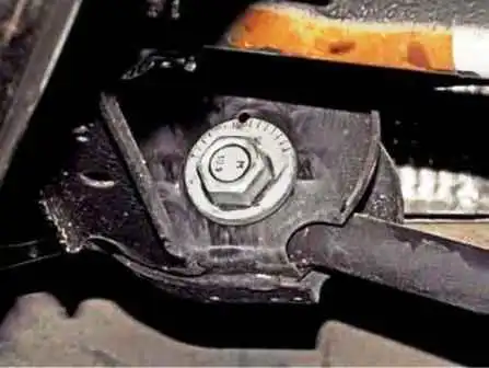
The position of the head of the adjusting bolt can be omitted.
Set the adjusting stop under the rear suspension knuckle and tighten the knuckle.
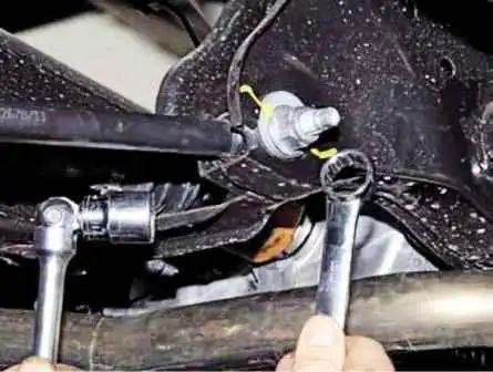
Using a 21 spanner wrench, unscrew the nut of the adjusting bolt securing the lever to the subframe, holding the adjusting bolt from turning with a head of the same size.
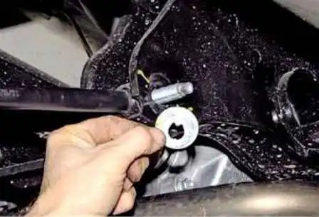
Remove the eccentric washer
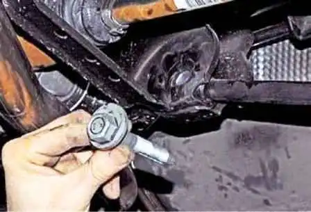
We remove the adjusting bolt from the holes of the subframe and the lever
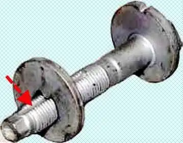
The bolt has a groove for fixing the washer in a certain position
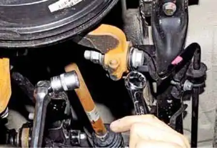
With a head of 21, we unscrew the nut of the bolt securing the arm eye to the rear suspension knuckle, holding the bolt from turning with a spanner wrench of the same size.
Remove the bolt or knock it out with a soft metal drift.
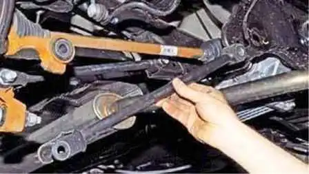
Remove the rear wishbone
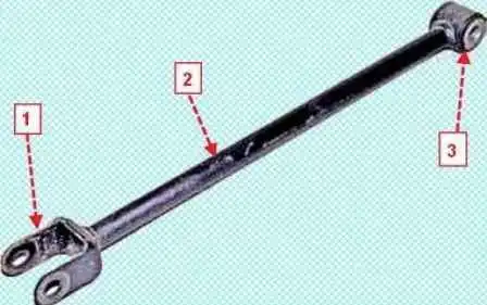
Install the lever in the reverse order, with the head of the adjusting bolt securing the lever to the subframe should be directed towards the front of the car; the mark made on the eccentric washer must match the mark on the subframe.
We finally tighten the nuts of the lever fastening bolts to the prescribed torque indicated at the beginning of the article in the “car on wheels” position.
Check and, if necessary, adjust the angles of the rear wheels.
Removing the front transverse arm
We install an adjustable stop under the rear suspension knuckle and tighten the fist.
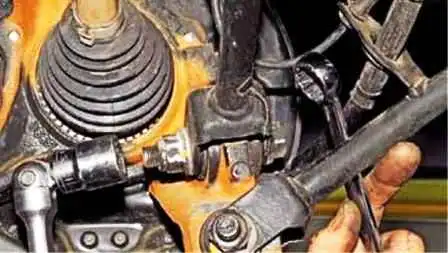
Using a 21 head, unscrew the nut of the bolt securing the arm eye to the rear suspension knuckle, holding the bolt from turning with a ring wrench at 21.
Remove the bolt or knock it out with a soft metal drift
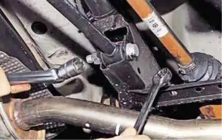
Head by 21 we unscrew the nut of the bolt securing the lever to the subframe, holding the bolt from turning with a ring wrench by 21
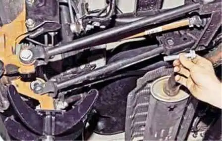
Remove the bolt from the holes of the lever and subframe
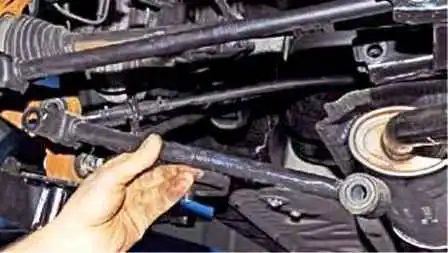
Remove the front transverse arm. Install the lever in reverse order
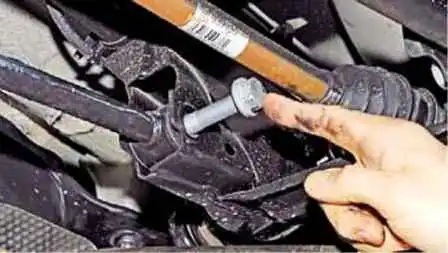
In this case, the head of the bolt securing the lever to the subframe should be directed towards the rear of the car.
We finally tighten the nuts of the lever mounting bolts to the moment described at the beginning of the article in the “car on wheels” position
Removing the trailing arm
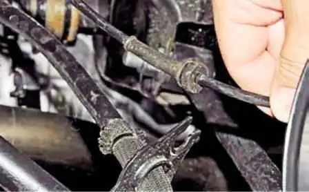
We remove the rubber bushing of the rear wheel speed sensor wiring harness from the trailing arm bracket
We disconnect the tip of the parking brake cable from the rear shoe lever (article - Replacing the rear wheel brake pads Renault Duster)
Remove the tip of the cable from the hole in the shield of the brake mechanism
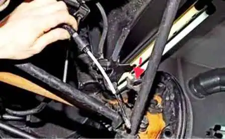
And from the hole in the trailing arm bracket.
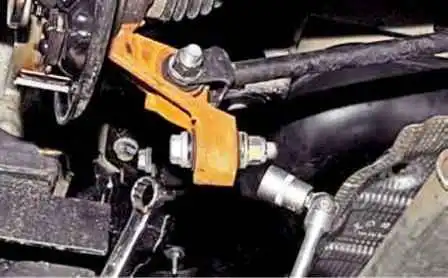
Set the adjustable stop under the rear suspension fist and tighten the fist
Using a 21 head, unscrew the nut that secures the arm eye to the rear suspension knuckle, holding the bolt from turning with a 21 ring wrench.
Remove the bolt or knock it out with a soft metal drift.
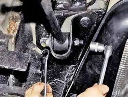
Using a 21 head, unscrew the nut of the bolt securing the lever to the body bracket, holding the bolt from turning with a 21 ring wrench.
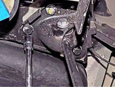
The length of the bolt does not allow it to be removed from the holes of the bracket and the lever, therefore, with an 18 head with an extension, unscrew the three bolts securing the bracket to the bottom of the body
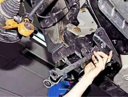
Remove the trailing arm together with the bracket.
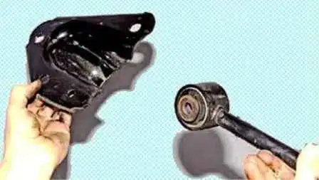
Remove the bolt and disconnect the lever from the bracket.
Install the trailing arm in reverse order.
We finally tighten the nuts of the lever mounting bolts to the moment indicated at the beginning of the article, in the “car on wheels” position.
Removing the fist
Remove the rear suspension knuckle to replace the rear wheel hub bearing, brake about the shield, to replace the fist assembly with bearing and silent blocks.
Unscrew the wheel bearing nut.
Remove the rear wheel and securely fix the car on a factory-made stand.
Remove the rear wheel speed sensor from the knuckle hole.
Remove the rear brake pads and disconnect the brake pipe fitting from the wheel cylinder.
We remove the tip of the parking brake cable from the hole in the shield of the brake mechanism.
We unscrew the nuts of the bolts of the shock absorber strut to the fist, take out the bolts and move the strut.
Disconnect the transverse and trailing arms from the knuckle as described above.
We remove the splined shank of the rear wheel drive outer hinge housing from the hub
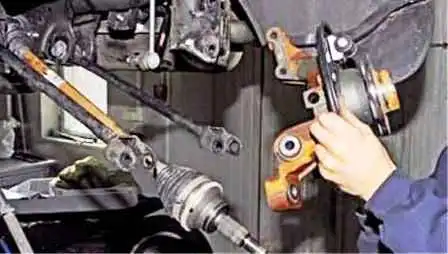
And remove the fist assembly with the hub and brake shield
Install the rear suspension knuckle in reverse order.
We finally tighten the nuts for fastening the two transverse levers and the trailing arm to the rear suspension knuckle to the torque described at the beginning of the article in the “car on wheels” position.
Replacing the rear wheel hub bearing
We replace the rear wheel hub bearing when it fails - noise, howl in the rear wheel area.
Showing the replacement of the left wheel hub bearing.
We replace the right wheel hub bearing in the same way.
Remove the fist assembly with the hub and the brake shield, as described above.
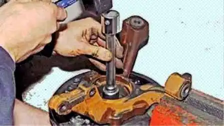
Clamping your fist in a vise, as shown in the photo, we strike the end of the hub with a hammer through a mandrel or tool head of a suitable diameter and press out the hub, on which one inner bearing ring usually remains.
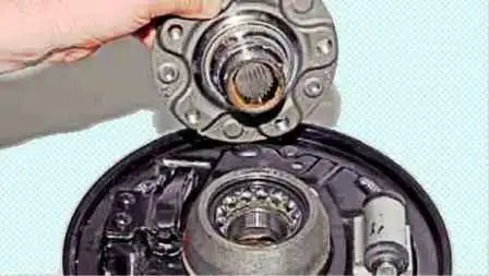
To remove this ring, clamp the hub flange in a vise.
We insert a chisel between the end of the inner ring of the bearing and the collar of the hub...
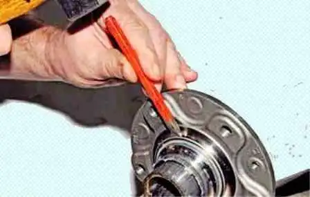
...and, striking the chisel with a hammer, we move the inner ring of the bearing along the hub.
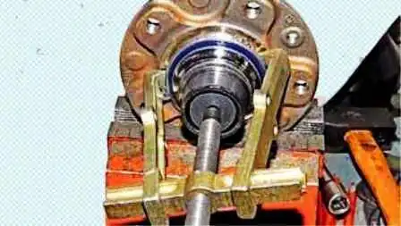
We hook the paws of the two-jaw puller on the inner ring of the bearing and finally press the inner ring of the bearing off the hub.
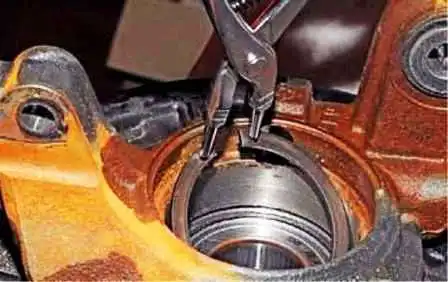
Using circlip pliers, remove the bearing circlip from the knuckle groove
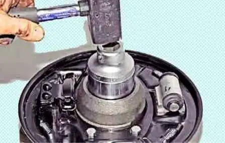
To press the bearing out of the knuckle, we rest the fist on the vise jaws and, striking with a hammer on the end face of the inner ring of the bearing through a mandrel or head of a suitable size, press the bearing out of the knuckle.
Before installing a new bearing, we clean the mounting hole in the fist and the groove for the retaining ring.
Using a file, we clean the nicks from the chisel on the hub.
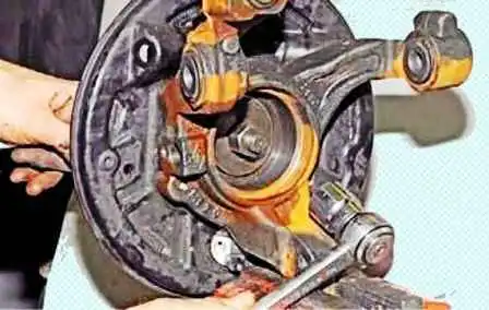
The bearing can be pressed in with a hammer or puller by applying pressure only to the outer ring of the bearing and resting the puller cup on the fist.

After pressing the bearing, we install a retaining ring in the groove of the fist.
Then we press the hub into the bearing, leaning with the puller cup on the inner ring of the bearing.
We carry out further assembly and installation of the fist in the reverse order.


