


The anti-lock braking system (ABS) consists of wheel speed sensors, a switch on the brake pedal, a hydroelectronic control module and warning lamps in the instrument cluster.
It includes an electronic brakeforce distribution system (EBD) and a self-diagnosis system that detects faults in the system components.
The ABS serves to regulate the pressure in the brake mechanisms of all wheels when braking in difficult road conditions and thereby prevents the wheels from locking.
The ABS system provides the following advantages:
- avoiding obstacles with a higher degree of safety, including during emergency braking;
- reducing the braking distance during emergency braking while maintaining the directional stability and controllability of the car, including in a turn.
In the event of a system fault, diagnostic functions and functions for maintaining operation in the event of system failures are provided.
The hydroelectronic control module receives information about the car's speed, direction of travel and road conditions from the wheel speed sensors and the throttle position sensor.
After the ignition is switched on, the control unit applies voltage to the wheel speed sensors, which use the Hall effect.
The sensors generate an output signal in the form of pulses.
The signal changes proportionally to the rotational frequency of the sensor's pulse ring.
On the basis of this information the control unit determines the optimal braking regime for the wheels.
The following operating regimes of the anti-lock system are distinguished:
Normal braking regime:
- During normal braking the inlet valve is open, the outlet valve is closed.
- When the brake pedal is pressed, brake fluid under pressure is supplied to the wheel cylinder and actuates the brake mechanisms of the wheels.
- When the brake pedal is released, the brake fluid returns to the master brake cylinder through the inlet valve and the check valve.
Emergency braking regime:
- If during emergency braking a wheel begins to lock, the module sends the pump's electric motor a command to reduce the supply of brake fluid, then voltage is applied to each solenoid valve.
- The inlet valve closes, and the supply of brake fluid from the master cylinder and the pump is cut off; the outlet valve opens, and the brake fluid flows from the wheel cylinder into the master cylinder and then into the reservoir, which causes a pressure drop.
Pressure holding regime:
- At the maximum pressure drop in the wheel cylinder, the module sends a command to hold the brake fluid pressure, voltage is applied to the inlet valve and not applied to the outlet valve.
- In this case the inlet and outlet valves are closed, and the brake fluid does not leave the wheel cylinder.
Pressure increase regime:
If the module determines that the wheel is not locked, no voltage is applied to the solenoid valves, the brake fluid passes through the inlet valve into the wheel cylinder, in which the pressure increases.
Diagnosis and repair of the anti-lock braking system require special equipment and tooling, therefore, in the event of its failure, contact a specialised technical service station.
Only the replacement of the wheel speed sensors and the hydroelectronic module is described here.
However, bear in mind that special equipment is required to remove air that may enter the valve system of the hydroelectronic module during unqualified removal.
That is why we do not recommend removing the module without extreme necessity.
Removing the ABS unit
We install the car on an inspection pit or a lift.
We mark the location of the pipes leading to the hydraulic unit.
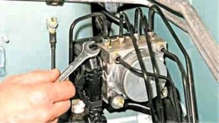
In the engine compartment on the right-hand side, with an 11 mm open-end spanner or a special spanner for brake pipe unions, we unscrew the unions of six brake pipes and disconnect the pipes from the hydraulic unit.
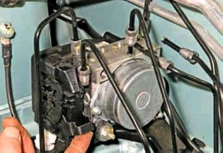
Having raised the wiring harness connector retainer…
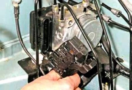
We disconnect the connector from the control unit.
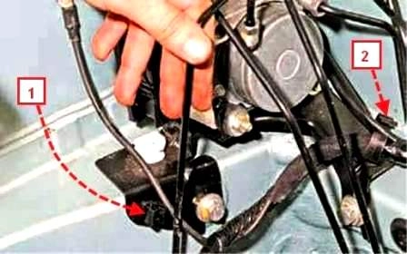
We bring the brake pipe out of holder 1 and the wiring harness out of holder 2 of the ABS unit bracket.
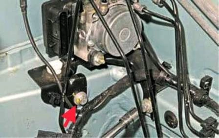
With a 13 mm socket we unscrew two bolts securing the ABS unit bracket to the body and remove the ABS unit with the bracket.
The ABS unit is secured to the bracket through two rubber bushes.
If the bushes are cracked or the rubber has lost its elasticity, we replace the bushes.
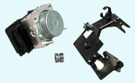
Having unscrewed with a 10 mm spanner two nuts securing the ABS unit to the bracket, we separate the unit and the bracket.
We install the ABS unit in the reverse order.
We bleed the brake hydraulic drive system (article — Replacement and bleeding of the brake and clutch hydraulic drive).
Removing the front wheel speed sensor
We raise the front part of the car.
We remove the front wheel arch liner.
We securely fix the car on a stand.
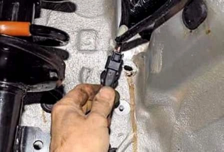
We take the wiring harness connector holder out of the opening in the body mudguard.
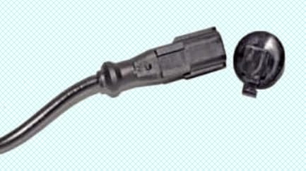
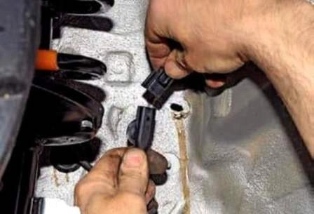
We press the retainer and disconnect the front harness connector from the sensor wiring harness connector.
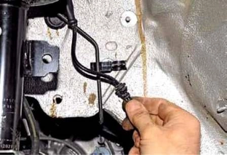
We bring the rubber sleeve of the sensor wiring harness out of the plastic holder located on the mudguard.
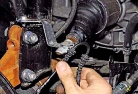
And two more sleeves — out of the holder located on the shock absorber strut.
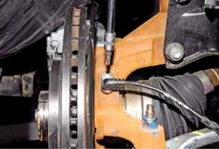
With a Torx T-30 key we unscrew the sensor securing screw to the steering knuckle.
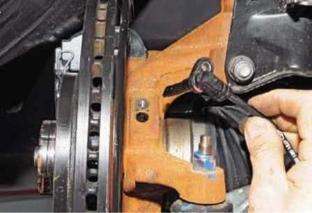
We remove the wheel speed sensor from the steering knuckle.
Before installation we clean the sensor installation site, as well as the sensor itself.
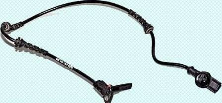
We install the sensor in the reverse order.
Removing the rear wheel speed sensor
We jack up the rear part of the car and remove the wheel.
We fix the car on a stand.
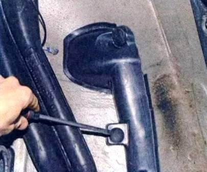
With a flat screwdriver we unscrew two plastic nuts securing the protective cover of the sensor wiring harness.
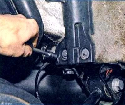
With a 10 mm socket we unscrew two cover securing nuts.
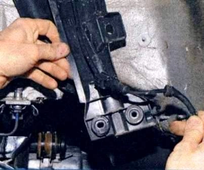
We move the cover away from the wheel arch and take the wiring harnesses out of the cover holders.
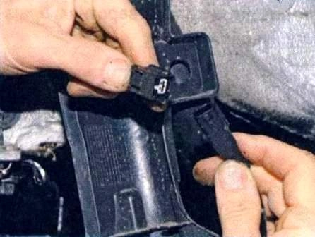
Having pressed the retainer, we disconnect the rear harness connector from the sensor wiring harness connector.
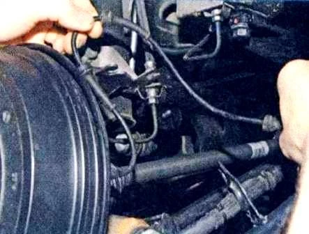
We bring the rubber sleeve of the sensor wiring harness out of the holder on the rear suspension arm.
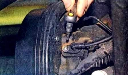
With a Torx T-30 key we unscrew the sensor securing screw.
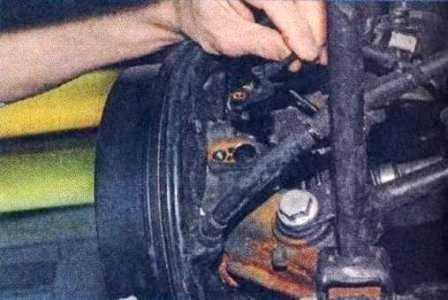
We remove the sensor from the opening in the knuckle.
We install the sensor in the reverse order.


