


The alternator is intended to generate electrical energy during the operation of the engine.
On the car is installed a three-phase alternating current alternator with electromagnetic excitation, a diode rectifier block and with a built-in voltage regulator.
The alternator is driven by a poly-V belt of the auxiliary drive from the crankshaft pulley.
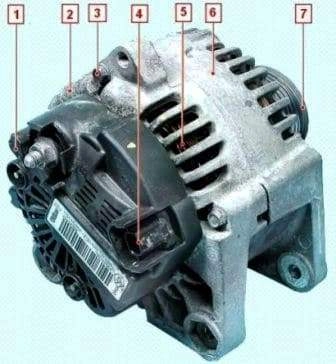
The alternator consists of the rotor, the stator, the rectifier block, the brush assembly with voltage regulator and two covers.
A pulley is installed on the rotor shaft.
For cooling the alternator parts, ventilation openings are made in its covers, and on the rotor on the side of the front cover a fan impeller is made.
In the stator a three-phase winding is made, connected in "star".
The winding terminals are soldered to the rectifier block.
The rectifier block is installed under the alternator cover together with the brush assembly and the voltage regulator.
In the rotor the excitation winding is made, the terminals of which are soldered to two slip rings.
The rotor shaft of the alternator rotates on two ball bearings.
The front bearing is pressed into the front cover of the alternator, and the rear one is pressed onto the rotor shaft and held on the rear cover of the alternator.
The voltage regulator — contactless, electronic, is combined with the brush assembly in a common non-detachable body.
The brushes — carbon, spring-loaded.
The model of the alternator with which the car is equipped depends on the type of engine installed.
For the K4M engine, the alternator model — Valeo TG11C063 8200667607 110A.
For the F4R 2.0 engine, the alternator model — Valeo TG12C092 231007562R 140A.
If the battery charge warning lamp has lit up on the instrument panel, do not rush to immediately remove the alternator for repair or replacement.
First make sure that the fault is caused by the failure of the alternator itself, and not by the wires of its electrical circuit or by the loosening of the drive belt tension.
Diagnosis of alternator faults
To carry out the work, a multimeter (in voltmeter mode with a measurement limit of 15—20 V) and a technical stethoscope will be required.
It is convenient to carry out the work with an assistant.
We prepare the car for technical maintenance and repair.
We check the condition of the auxiliary drive belt.
Wear of the drive belt leads to its slipping on the pulley and does not allow the alternator to develop the necessary power.
Indirectly, the slipping of the belt can be determined by the dim glow of the headlights in the dark and by the whistling sound in the front part of the engine when sharply pressing the accelerator pedal.
We start the engine and observe the battery charge warning lamp on the instrument panel (it must light up when the ignition is switched on and go out after the engine starts).
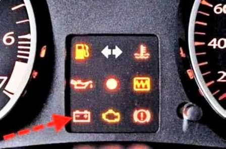
If the battery charge warning lamp does not go out after the engine starts, check the supply of +12 V voltage to the excitation winding of the alternator.
To do this, disconnect the wire connector from terminal 4 (figure 1) of the alternator and measure the voltage on it with a multimeter in voltmeter mode.
If the voltage does not arrive, it is necessary to check the supply circuit, the protection and switching block in accordance with the electrical equipment diagram of the car.
We warm up the engine to operating temperature (not less than 80 °C).
We switch on all powerful consumers of electrical energy of the car: rear window heating, electric fan of the climate installation, main beam of the headlights.
The assistant, pressing the accelerator pedal and controlling the operation of the engine by the tachometer, maintains the rotational frequency of the engine crankshaft within 3000—3500 min-1.
In the absence of an assistant, the multimeter can be connected to the battery using two lengths of wire.
The length of the wires must be sufficient so that the device can be placed in the car interior.
With a multimeter in voltmeter mode we measure the voltage at the battery terminals.
With a serviceable alternator, the voltmeter must show a voltage not lower than 14 V.
If the voltage is lower, possibly the auxiliary drive belt is worn, the alternator circuit is faulty, the voltage regulator is faulty, the brushes in the alternator are oil-contaminated or worn, or the alternator itself is faulty.
A disturbance in the operation of the alternator may be caused by poor electrical contact in the connections due to formed oxides.
We disconnect the terminal and the wire connector from the alternator (see below) and treat them with a means for cleaning and protecting electrical contacts.
Removing and installing the alternator
We disconnect the negative terminal of the battery.
We remove the front bumper (article — Removing and installing the bumpers).
We remove the auxiliary drive belt and the support roller (article — Checking and replacing the auxiliary drive belt).
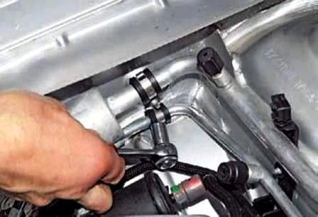
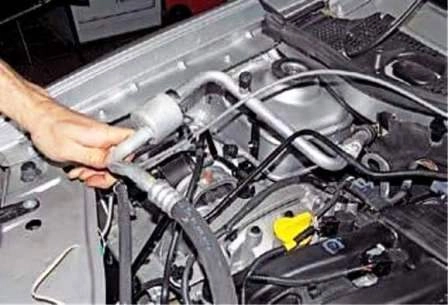
With a 10 mm socket we unscrew the nut securing the holders of the air conditioning pipes on the engine compartment mudguard.
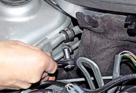
With a 10 mm socket we unscrew the nut securing the holders of the air conditioning pipes on the mudguard cup.
We remove the pipe holders from the studs.
We unscrew two bolts securing the power steering radiator.
We remove the radiator deflector.
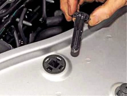
We remove the retainer of the upper support of the electric fan shroud.
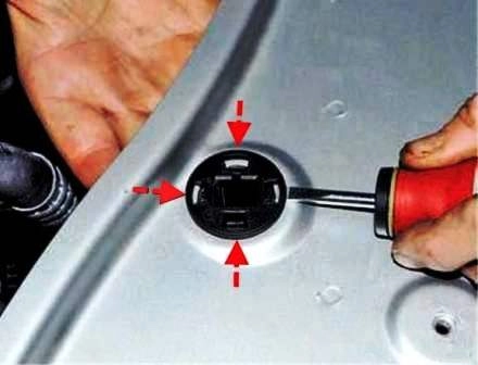
Pressing with the hand from below the bush of the upper support of the fan shroud, with a screwdriver we press on the four retainers of the bush.
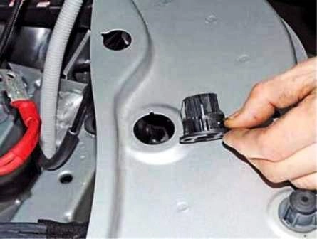
We remove the bush from the opening in the upper cross member of the radiator frame.
We also remove the other bush of the upper support of the fan shroud.
Having lifted the fan, we bring the lower supports of the fan shroud out of the openings in the subframe and, having shifted the radiator forward in the direction of travel of the car, we place the lower supports of the fan shroud on the subframe.
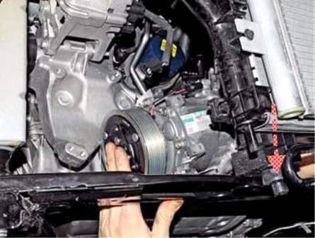
Having disconnected the wire connector from the air conditioning compressor connector and unscrewed its securing bolts, we move the compressor aside and place it on the subframe (the arrow shows the lower support of the fan shroud).
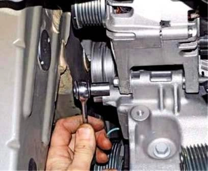
With a 10 mm socket we unscrew the lower bolt securing the alternator.
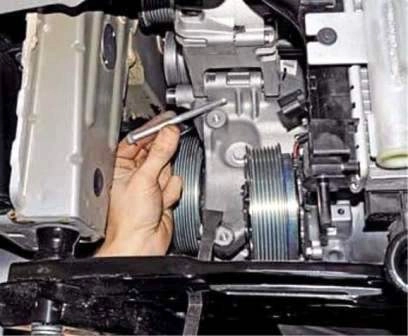
We remove the bolt.
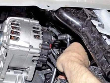
With a 13 mm socket we unscrew the nut securing the wire terminal.
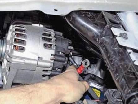
We remove the wire terminal from the alternator terminal.
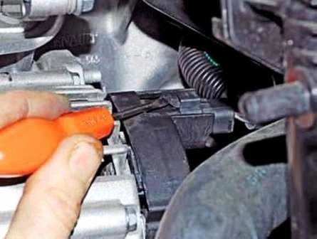
With a screwdriver we prise off the retainer of the wire connector.
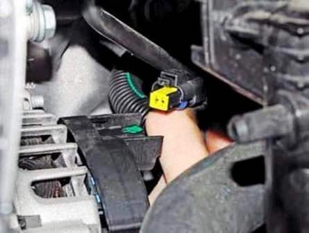
We disconnect the connector from the alternator.
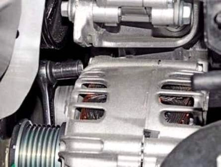
With a 10 mm socket we unscrew the upper bolt securing the alternator.
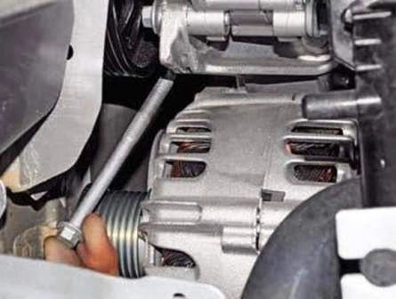
We remove the bolt.
With a mounting spatula we prise the alternator to move the threaded bushes of the alternator away from the bracket.
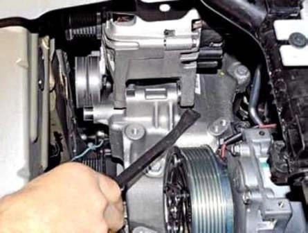
We remove the alternator from the engine compartment.
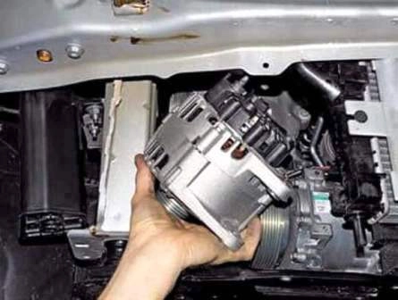
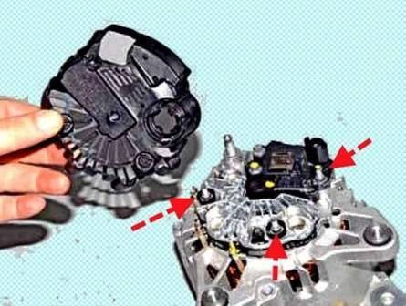
Having prised up with a screwdriver, we shift the alternator cover off the three studs.
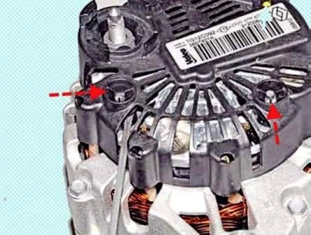
We remove the cover (the arrows show the studs securing the cover).
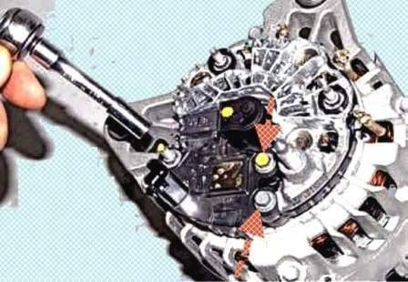
With a 7 mm socket we unscrew by the hexagon the stud and two bolts securing the brush holder.
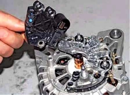
We remove the brush holder with the voltage regulator assembled.
To check the voltage regulator we connect to the brushes a lamp (1—3 W, 12 V), and to the terminals of the brush holder a direct current source, first with a voltage of 12 V, and then 15—16 V.
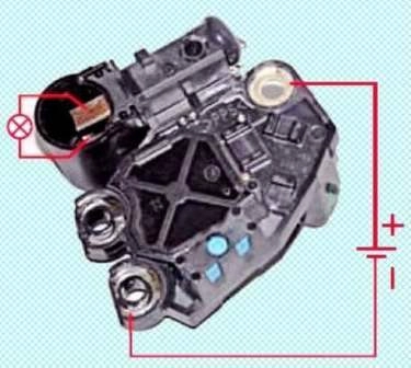
In the first case the lamp must light, in the second — not.
If the lamp lights in both cases — there is a breakdown in the regulator, if it does not light — there is a break or disturbed contact between the terminals of the voltage regulator and the brushes.
In both cases the brush holder with the voltage regulator must be replaced.
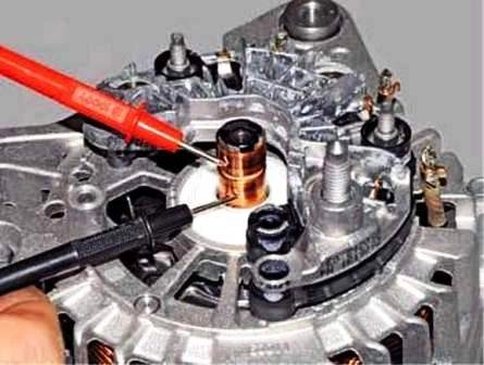
To check a break in the rotor winding we connect the probes of a digital tester (in ohmmeter mode) to the slip rings.
If the tester shows infinity, it means there is a break in the winding.
To check a short circuit of the rotor winding to earth we connect the probes of the tester (in ohmmeter mode) to the slip ring and the alternator body.
The tester must show infinity, otherwise the winding is short-circuited to earth.
In both cases the rotor or the alternator must be replaced.
We inspect the stator windings, on the insulation of the windings there must be no traces of overheating, which is a consequence of a short circuit in the valves of the rectifier block.
If on the windings there are traces of overheating, it is necessary to replace the stator or the alternator.
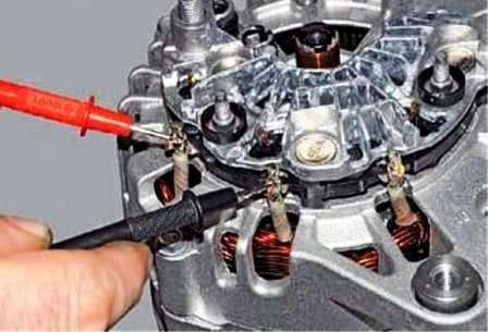
To check a break in the stator windings we connect the probes of the tester (in ohmmeter mode) to the terminals of the windings.
If the tester shows infinity, it means there is a break in the winding and the stator or the alternator must be replaced.
We also check the other stator windings.
To check a short circuit of the stator winding to earth we connect the probes of the tester (in ohmmeter mode) to the terminal of the winding and the alternator body.
The tester must show infinity, otherwise the winding is short-circuited to earth and the stator or the alternator must be replaced.
We also check the other windings.
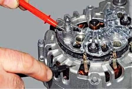
To check the diodes of the rectifier block we connect the plus of the digital tester (in diode test mode) to the "В+" terminal of the alternator, and the minus to its body.
The tester must show infinity.
Otherwise, both in the block of positive and in the block of negative diodes there is a short circuit.
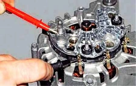
To check for a short circuit in the positive diodes we connect the plus of the tester (in diode test mode) to the "В+" terminal of the alternator, and the minus — to the terminal of one of the phase windings of the stator.
The tester must show infinity.
If the tester shows the presence of a circuit, one or several positive diodes are broken down.
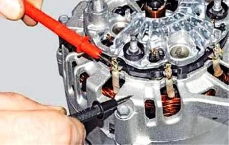
To check for a short circuit in the negative diodes we connect the plus of the tester (in diode test mode) to the terminal of one of the phase windings of the stator, and the minus — to the alternator body.
The tester must show infinity.
If the tester shows the presence of a circuit, one or several negative valves are broken down.
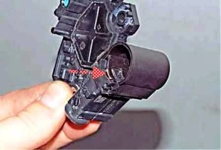
Before installing the brush holder we recess the brushes and, having shifted the brush cover, we fix the brushes.
We install the brush holder in place, screw in and tighten the bolts and the stud securing the brush holder.
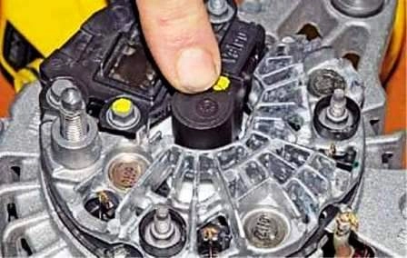
Having pressed on the cover, we release the brushes, which under the action of the springs will advance to the slip rings.
We put the alternator cover in place.
Before installing the alternator we shift the threaded bushes towards the alternator cover by 2—4 mm.
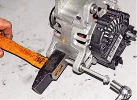
To do this, having rested the hammer against the alternator eye, we screw into the bush the bolt securing the alternator until it stops against the hammer and, turning the bolt with a 10 mm socket, we shift the bush.
We also shift the other threaded bush.
We install the alternator in the reverse order.
Alternator repair
For the repair of the alternator, keys 7, 10, 27, a Torx T-50 key, a tester, a puller, a hammer, screwdrivers will be required.
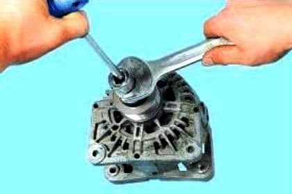
Holding the shaft against turning, we unscrew the nut securing the pulley.
We remove the pulley and the distance ring.
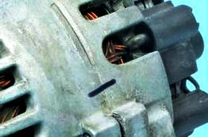
We mark with a marker the mutual position of the covers and the stator body.
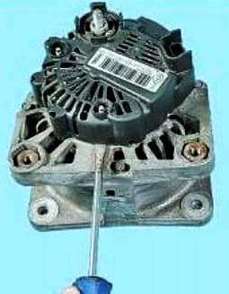
We prise up the edge of the cover with a flat-blade screwdriver.
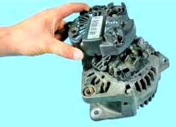
We remove the cover.
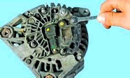
We unscrew two bolts securing the brush holder.
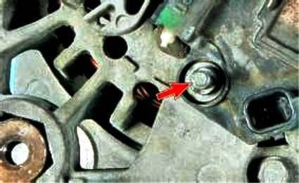
We unscrew the nut securing the brush holder.
We remove the brush holder assembled with the voltage regulator.
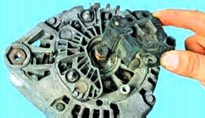
We check the protrusion of the brushes.
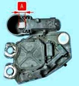
If dimension "А" is less than 5 mm, we replace the brush assembly.
We also check the ease of movement of the brushes.
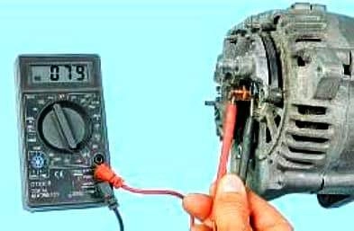
We check the resistance of the rotor winding.
The readings of the tester must show infinity, otherwise there is a break in the rotor winding and we replace the rotor.
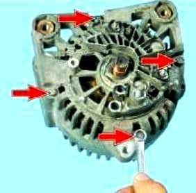
We unscrew four tightening bolts.
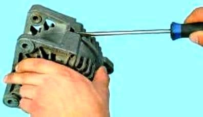
We insert a screwdriver between the covers to separate them.
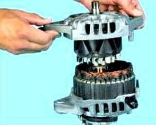
We remove the cover from the drive side together with the rotor.
We press the rotor out of the front bearing.
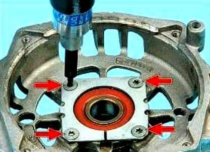
To replace the front bearing of the rotor we unscrew four screws securing the pressure plate.
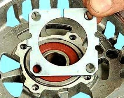
We remove the plate.
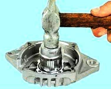
We press the bearing out of the cover.
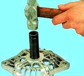
We press with a mandrel of suitable size the new bearing into the cover, applying force to the outer ring.
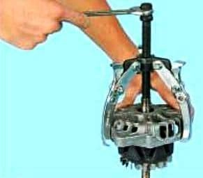
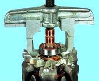
We pull the bearing off the rotor shaft using a puller.
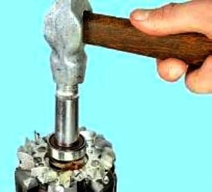
We press the new bearing onto the rotor shaft until it stops, applying force to the inner ring of the bearing.
We check the absence of a short circuit of the rotor winding to the body, having connected alternately to each slip ring and to the rotor body.
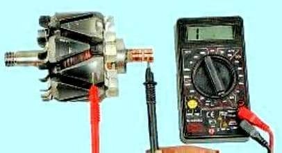
The tester must show infinity.
We assemble the alternator in the reverse order.
We orient the covers according to the established marks.


