
The driveline transmits torque from the transfer case to the rear gearbox.
The cardan gear consists of front and rear shafts, an intermediate elastic bearing with a bearing and two cardan joints.
The cardan shafts are made of thin-walled steel pipes and have different pipe diameters.
The design of the driveline, consisting of two shafts, allows you to increase the critical speed.
To compensate for the angular and axial movements of the power plant and the rear suspension, an internal hinge is installed in the rear of the front driveshaft.
The connection to the inner joint is covered with a rubber boot and is completely sealed.
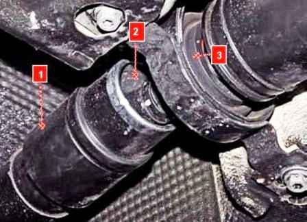
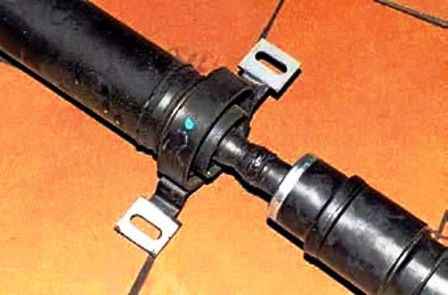
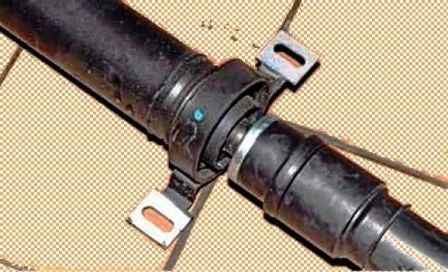
The front end of the rear driveshaft is installed in the intermediate support.
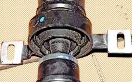
The support consists of a deep groove ball bearing mounted in a bracket inside a rubber cushion.
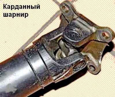
To eliminate uneven rotation, two identical cardan joints are used, and their forks located at the ends of the cardan shafts must lie in the same plane.
In this case, the uneven rotation caused by one universal joint is compensated by the unevenness of the other.
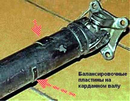
The cardan shafts are dynamically balanced on special stands.
The imbalance is balanced by welding balancing plates to the shaft tube.
An imbalance in the driveline leads to noticeable vibrations at high speeds (over 60-80 km/h).
Strong imbalance can cause destruction of the driveline and neighboring nodes.
The cardan gear has a non-separable design and, in case of wear or damage, is replaced as an assembly.
External signs of driveline malfunctions are: increased noise, vibration, knocking when starting off and shifting gears.
The reasons for these phenomena can be increased wear of the bearings and crosses in the hinges, the bearing of the intermediate support, the loss of balancing plates, loosening of the bolts securing the flanges of the propeller shaft forks to the flanges of the electromagnetic clutch and transfer case.
Removing the driveline
We install the car on a lift or overpass.

Using a 16 spanner wrench, unscrew the bolt securing the rear propeller shaft joint yoke to the electromagnetic clutch flange
Sliding the shaft forward, we remove the centering collar of the yoke flange from the flange of the electromagnetic coupling.

We tie the cardan joint to the flange of the electromagnetic clutch

With a 13 head, unscrew the two bolts fixing the bracket of the intermediate support to the bottom of the body

Using a 16-head with an extension, unscrew the bolts securing the front driveshaft hinge yoke to the transfer case output shaft flange

Sliding the cardan shaft back, remove the centering shoulder of the yoke flange from the transfer case output shaft flange

Removing the driveline
Install the driveline in reverse order.

")
")
")
")
")
")
")
")