The Renault Duster is equipped with two independent braking systems: service and parking.
The first, equipped with a hydraulic drive and vacuum booster, provides braking when the vehicle is moving, while the second brakes the vehicle when parked.
The service system is dual-circuit with a diagonal connection of the front and rear brake mechanisms.
One hydraulic circuit operates the right front and left rear brake mechanisms, the other operates the left front and right rear brake mechanisms.
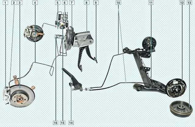
If one of the circuits of the service braking system fails, the second circuit is used, ensuring that the vehicle stops with sufficient efficiency.
A vacuum booster is included in the hydraulic drive.
The vehicle is equipped with Anti-lock braking system (ABS).
The vehicle is equipped with a cable-operated parking brake system on the rear wheel brake mechanisms.
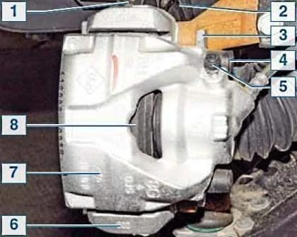
The front wheel brake mechanism is a disc brake with automatic adjustment of the gap between the pads and the disc, with a floating caliper.
The sliding caliper is formed by a caliper with a single-piston working cylinder.
The shoe guide is bolted to the steering knuckle.
The sliding caliper is bolted to the guide pins installed in the holes in the shoe guide.
The guide pins are lubricated with grease Lubricated and protected by rubber boots.
A piston with an O-ring is installed in the working cylinder cavity.
The elasticity of this ring maintains an optimal gap between the pads and the ventilated disc.
When braking, the piston, under the influence of fluid pressure, presses the inner pad against the disc. As a result of the reaction force, the caliper moves on its pins, and the outer pad is also pressed against the disc, while the contact force between the pads is equal.
When releasing the brakes, the piston is moved away from the pad due to the elasticity of the O-ring, creating a small gap between the pads and the disc.
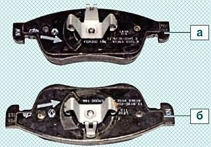
The brake mechanisms of the left and right front wheels are not interchangeable.
The inner brake pads are also not interchangeable. They differ in the location of the recesses on the anti-vibration and anti-squeak steel plastic.
The inner pads are marked with arrows indicating the direction of wheel rotation.
If the pads are reversed during installation, they will squeal when braking.
The tandem-type master cylinder of the hydraulic brake drive is mounted in the engine compartment directly on the brake booster.
It consists of two separate chambers connected to independent hydraulic circuits.
The first chamber is connected to the right front and left rear brake mechanisms, the second to the left front and right rear.
A reservoir is mounted to the master cylinder via rubber connecting bushings. Its interior is divided by partitions into three compartments.
Each of the two main compartments feeds one of chambers of the master brake cylinder, and the third chamber supplies power to the clutch release master cylinder.
When the brake pedal is pressed, the master brake cylinder pistons begin to move, the sealing lips close the expansion holes, the chambers and reservoir separate, and brake fluid begins to be expelled.
A brake fluid level sensor is installed in the reservoir cap.
When the fluid level drops below the permissible level, the brake system malfunction indicator light comes on in the instrument cluster.
The flange for connection to the brake booster is sealed with a rubber ring.
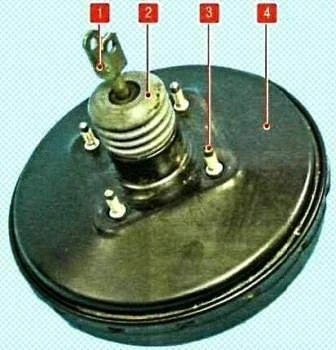
The vacuum booster, installed between the pedal mechanism and the master cylinder, creates additional braking force proportional to the pedal force due to the vacuum in the engine intake manifold through the piston rod and the first chamber of the master cylinder.
The hose connecting the vacuum booster to the intake manifold is made integral with a check valve inserted through a rubber grommet into the booster housing.
The valve maintains the vacuum in the booster as it drops in the intake manifold and prevents the fuel-air mixture from entering the vacuum booster.
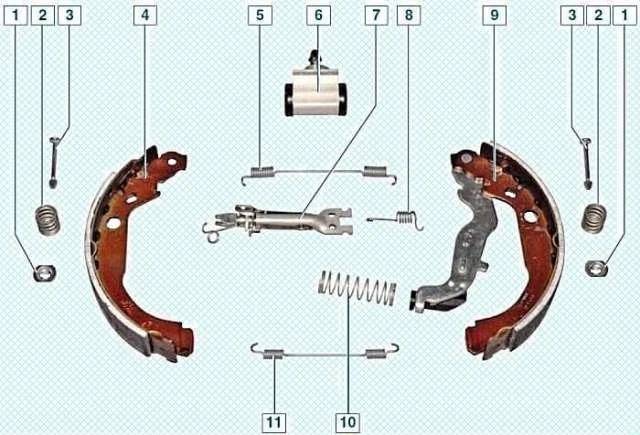
Rear wheel brake mechanism drum with automatic adjustment of the gap between the shoes and the drum.
The brake shoes are actuated by one hydraulic working cylinder with two pistons.
Optimum clearance between the drum and the shoes is maintained by a mechanical adjuster mounted on the spacer bar bar.
As the brake shoe linings wear, the shackle rotates the adjuster nut and its threaded end lengthens, compensating for the increasing gap between the spacer bar and the front shoe rib.
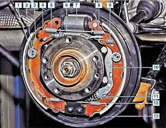
The rear brake mechanisms of 4x2 and 4x4 vehicles are almost identical.
The differences are only related to the design of the brake drums.
On all-wheel drive vehicles, the brake drum is attached to the hub, and on front-wheel drive vehicles, the brake The drum itself is part of the rear wheel bearing assembly, and the bearing is pressed into it.
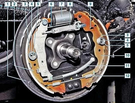
The automatic clearance adjustment mechanism consists of a composite spacer bar of the shoes, the adjuster lever and its spring.
It begins to work when the gap between the brake pads and the brake drum.
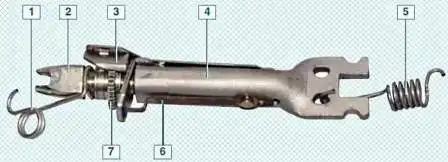
When the brake pedal is pressed, the wheel cylinder pistons cause the brake pads to move apart and press against the drum, while the adjuster lever protrusion moves along the groove between the teeth of the ratchet nut.
When the brake pads reach a certain wear level and the brake pedal is pressed, the adjuster lever has enough travel to rotate the ratchet nut by one tooth, thereby increasing the length of the spacer bar and simultaneously decreasing the clearance between the brake pads and drum.
This gradual lengthening of the spacer bar automatically maintains the gap between the brake drum and the shoes.
The wheel cylinders of the rear brake mechanisms are identical.
The front brake shoes of the rear wheels are identical, but the rear ones differ – they have non-removable parking brake levers mounted on them in a mirror-symmetrical manner.

The expander bar and ratchet nut of the brake mechanisms of the left and right wheels (of a 4x4 vehicle) are different.
The ratchet nut and the end of the expander bar of the left wheel have a right-hand thread, and the ratchet nut and the end of the expander bar of the right wheel have a left-hand thread.
The brake adjuster levers of the left and right wheels are mirror-image symmetrical.
The vehicle is equipped with an anti-lock braking system (ABS).
Fluid from the master cylinder enters the ABS unit, and from there it is supplied to the brake mechanisms of all wheels.
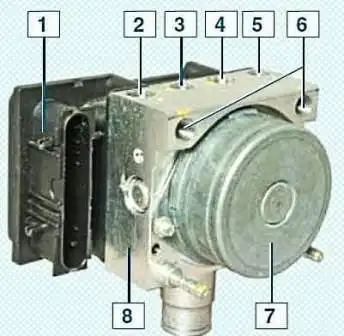
The ABS unit, mounted in the engine compartment on the right side member near the front shield, consists of a hydraulic unit, modulator, pump, and control unit.
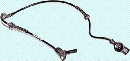
The ABS operates depending on signals from inductive wheel speed sensors.
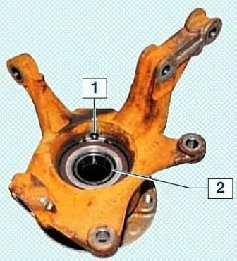
The front wheel speed sensor is located in the wheel hub assembly - inserted into the hole in the steering knuckle.
The sensing disc of the front wheel speed sensor is the protective washer of the hub bearing, located on one of the two end surfaces of the bearing.
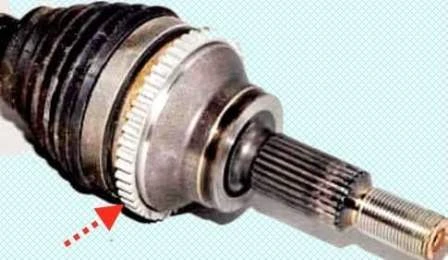
This dark-colored washer is made of magnetic material.
On the other end surface of the bearing is a standard light-colored protective washer.
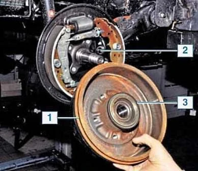
The rear wheel speed sensor on a 4x2 vehicle is mounted on the brake backing plate, and the reference plate of the sensor is a ring made of magnetic material pressed onto the flange of the brake drum.
The rear wheel speed sensor on a 4x4 vehicle is located in the wheel hub assembly - a hole is inserted into the knuckle.
When the vehicle brakes, the ABS control unit detects the onset of wheel lockup and opens the corresponding electromagnetic valve of the modulator to relieve the pressure of the working fluid in the channel.
The valve opens and closes several times per second, so you can confirm that the ABS is working by a slight vibration of the brake pedal during braking.
If an ABS malfunction occurs The braking system remains functional, but the wheels may lock.
In this case, a corresponding fault code is written into the control unit's memory, which is read using special equipment at a service center.
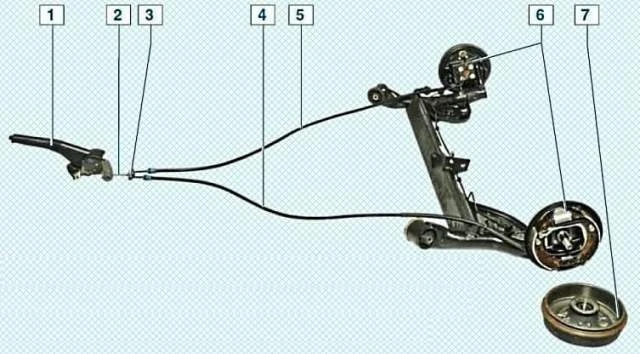
The parking brake drive is manual, mechanical, cable-operated, on the rear wheels.
It consists of a lever, a front cable with an adjusting nut on its end, an equalizer, two rear cables, and levers in the brake mechanisms of the rear wheels.
The parking brake lever, fixed between the front seats on the floor tunnel, is connected to the front cable.
An equalizer is attached to the rear end of the front cable, into the holes of which the front ends of the rear Cables.
The rear ends of the cables are connected to the parking brake actuator levers, which are secured to the rear brake shoes.
During operation (until the rear brake shoes are completely worn out), the parking brake actuator does not require adjustment, since the extension of the brake mechanism spacer bar compensates for the wear of the shoes.
The parking brake actuator only needs to be adjusted if the cables or parking brake lever are replaced.
Possible Brake System Malfunctions and Correction Methods
- - Cause of Malfunction - Remedy
Increased brake pedal travel:
- - Brake fluid leak from the wheel cylinders - Replace the faulty wheel cylinders, flush and dry the pads, discs, and Drums
- - Air in the brake system. - Bleed the system.
- - Damaged rubber seals in the master cylinder. - Replace the master cylinder.
- - Damaged rubber hoses of the brake hydraulic system. - Replace the hoses and bleed the system.
- - Excessive brake disc runout (more than 0.03 mm) - Grind or replace the disc if the thickness of the brake disc at the front of the wheel is less than 19.8 mm.
Insufficient braking efficiency:
- - Oily brake pad linings. - Flush and dry the pads.
- - Seized pistons in the working cylinders. - Eliminate the cause of seizure, replace damaged parts.
- - Brake pad linings are completely worn out - Replace the brake pads.
- - Brake mechanisms are overheating - Stop immediately and allow the brake mechanisms to cool.
- - Using low-quality pads - Use original pads or products from companies specializing in the production of brake system components.
- - A leak in one of the circuits (accompanied by a failure of the brake pedal) - Replace damaged parts, bleed the system.
- - Incorrect brake pedal position - Determine the cause of the increase in full travel and replace damaged parts.
- - Incorrect adjustment of the brake booster rod protrusion - Contact a service center to adjust the booster.
- - Malfunction of the anti-lock braking system Brake system (ABS) - Contact a service center to have the anti-lock brake system checked.
- - Incomplete release of all wheels - Replace the master cylinder.
- - No free play in the brake pedal.
- - Increased protrusion of the brake booster rod - Contact a service center to have the booster adjusted.
- - Swelling of the rubber seals of the master cylinder due to gasoline, mineral oils, etc. getting into the fluid. - Flush and bleed the entire hydraulic system, replace rubber components.
- - Seized master cylinder pistons - Check and replace the master cylinder if necessary.
Braking of one wheel with the pedal released:
- - Fractured or weakened parking brake shoe tension springs - Replace the spring.
- - Piston sticking in the slave cylinder due to contamination or corrosion of the housing - Replace the slave cylinder and bleed the brake hydraulic system.
- - Swelling of the slave cylinder sealing rings due to foreign impurities entering the fluid - Replace the slave cylinder and bleed the brake hydraulic system.
- - Incorrect position of the caliper relative to the brake disc when the mounting bolts are loose. - Tighten the mounting bolts; replace any damaged components if necessary.
- - Incorrect parking brake adjustment - Adjust the parking brake system.
- - Malfunction of the anti-lock braking system - Have the anti-lock braking system checked at a service center.
The vehicle skids or pulls to one side when braking:
- - Seized piston of the working cylinder - Check and eliminate the seizure of the piston in the cylinder.
- - Blockage of any tube due to a dent or clog - Replace or clean the tube.
- - Dirt or oil on the discs, drums, and linings of the brake shoes - Clean the brake components.
- - Incorrect wheel alignment - Adjust the wheel alignment.
- - Uneven tire pressure - Set the correct pressure. Tires
- - One of the brake system circuits is not working (accompanied by a decrease in braking efficiency) - Replace damaged components and bleed the system. If this does not produce the desired result, have the anti-lock brake system (if equipped) checked at a service center.
Increased brake pedal effort when braking:
- - The vacuum booster is faulty - Replace the booster
- - The hose connecting the vacuum booster to the engine intake manifold is damaged or loose - Replace the hose
- - Swelling of the rubber cylinder seals due to gasoline, mineral oils, etc. getting into the fluid. - Replace the cylinders, flush, and bleed the system.
Brake squealing or vibration:
- - Oily friction linings - Clean the linings with a wire brush and warm water with detergent. Eliminate the causes of fluid or grease getting on the brake pads.
- - Worn linings or foreign particles in them - Replace the pads.
- - Excessive runout or uneven wear (felt by vibration in the brake pedal) of the brake disc - Grind or replace the disc if the thickness of the front brake discs is less than 19.8 mm.


