A car with a manual transmission is equipped with a single-plate, dry clutch with a central diaphragm spring.
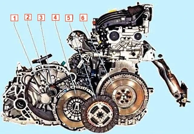
The clutch disc (basket) is connected to the engine flywheel with six bolts.
Three pins are pressed onto the flywheel, which center the clutch housing.
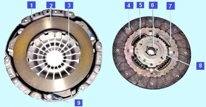
A diaphragm spring, stamped from sheet spring steel, is installed in the drive disc housing.
In its free state, the spring has the shape of a truncated cone with radial slots extending from the inner edge of the spring.
The slots in the spring form eighteen petals, which are elastic release levers.
Due to the elasticity of the levers, the diaphragm spring creates a more uniform pressure on the clutch pressure plate, which facilitates smooth engagement. and disengaging the clutch.
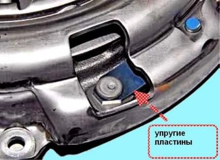
The clutch housing is connected to the pressure (driving) plate at three points by elastic steel plates.
The housing with the diaphragm spring and the pressure plate form a non-separable unit (also called the clutch "basket"), which is balanced on a stand.
If the clutch basket fails, it is replaced entirely.
Replacing the "basket" is necessary in case of severe annular wear of the diaphragm spring petals and in the event that The ends of the petals are not aligned.
We also replace the clutch basket if the pedal force decreases when disengaging the clutch (and, accordingly, the working stroke increases), which indicates significant wear on the pressure plate surface or "settling" of the diaphragm spring.
The driven disk with a spring-loaded torsional vibration damper is located on the splines of the transmission input shaft between the engine flywheel and the pressure plate.
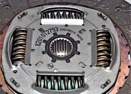
The torsional vibration damper dampens vibrations caused by dynamic loads in the transmission and uneven engine operation.
Two friction linings of the disc are riveted on both sides to a spring plate, which in turn is riveted to one of the two damper plates.

The spring plate has a wave shape.
When the clutch is engaged, the friction linings compress the spring plate, which facilitates smooth clutch engagement.
The disc hub is mounted between the damper plates.
The damper springs are mounted in grooves in the hub and damper plates.
The damper plates are connected by support posts.
The disc hub, opposite the support posts, has cutouts that allow the hub to rotate within a certain range relative to the damper plates, compressing the damper springs.
This helps reduce dynamic loads in the transmission when starting the vehicle and shifting gears.
On the driven disc hub in a plastic housing An idle damper is located here, which serves to eliminate knocking in the gearbox when the engine is idling.
The driven disk is replaced if its axial runout in the area of the friction linings exceeds 0.5 mm, if there is oiling, cracking, scoring or uniform wear of the linings, if the riveted joints are loose, or if The distance between the working surface of the lining and the rivet head is less than 0.2 mm.
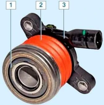
The hydraulic slave cylinder is made as a single unit with the clutch release bearing (release bearing) and is located inside the clutch housing.
The slave cylinder is attached to the clutch housing.
The moving part of the slave cylinder is connected to a bearing, which can move along the input shaft of the gearbox.
A spring (covered with a rubber corrugated boot) located between the cylinder and the bearing race constantly presses the bearing against the diaphragm spring of the clutch basket.
Therefore, there are no gaps in the clutch mechanism and no adjustment is provided.
Closed release bearing type.
The bearing contains grease.
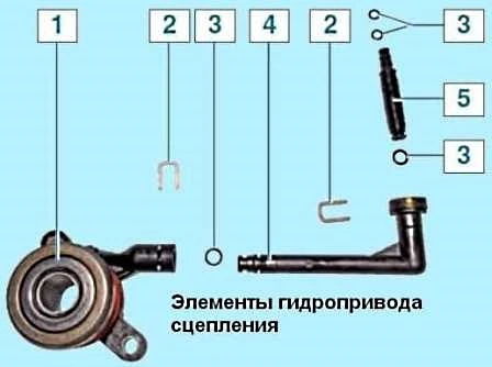
The clutch hydraulic drive consists of a master and slave cylinder, which are connected by a pipe.
The working fluid is poured into a reservoir mounted on the master cylinder.
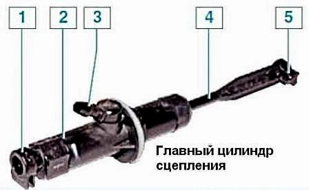
The clutch master cylinder is connected to the reservoir with a rubber hose.
The master cylinder is mounted on the front panel, and its piston rod is connected to the clutch pedal.
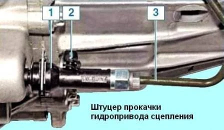
To bleed the clutch hydraulic drive, a nipple covered with a rubber cap is located on the plastic tip of the hydraulic drive tube.
The clutch is disengaged as follows.
When the pedal is pressed, fluid pressure is generated in the clutch release hydraulic system.
The fluid pressure is transmitted to the piston of the slave cylinder, which moves the clutch release bearing along the axis of the transmission input shaft.
The bearing presses on the petals of the diaphragm spring of the pressure plate.
The spring, deforming, moves the pressure plate, as a result of which the pressure plate stops pressing the driven disk against Flywheel.
The engine crankshaft and gearbox input shaft can rotate independently of each other in this case.
When the clutch pedal is released, the bearing returns to its original position, causing the diaphragm spring to again press on the pressure plate, which in turn presses the driven plate against the flywheel. As a result, torque transmission is resumed.
Bleeding the Clutch Hydraulic System
Bleeding the clutch hydraulic system to remove air after depressurization occurs when replacing the clutch master or slave cylinders, lines, and hoses, as well as when removing the brake master cylinder or reservoir for the brake and clutch hydraulic systems.
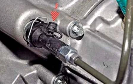
To bleed the clutch hydraulic system, a nipple covered with a rubber cap is located on the plastic end of the hose.
The adapter onto which the end of the hose is mounted is not secured in the clutch housing. Therefore, for ease of bleeding, we recommend making a lock washer for the adapter from a metal washer (1.0-1.2 mm thick, 23 mm outer diameter, and 10.5 mm hole diameter).
Before bleeding, check the fluid level in the tank. Add fluid if necessary.
Install the manufactured lock washer into the adapter groove (shown with the tube tip removed for clarity).
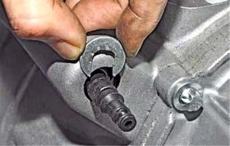
Remove the protective cap from the bleeder nipple.
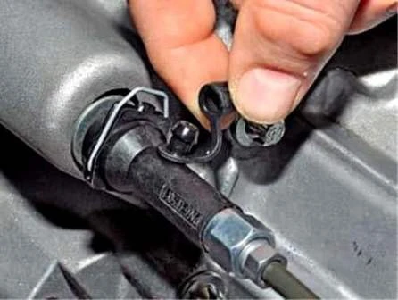
Place a transparent hose on the fitting and lower the other end into a container partially filled with hydraulic fluid so that the free end of the hose is submerged.
Have the assistant press the clutch pedal several times and hold it down.
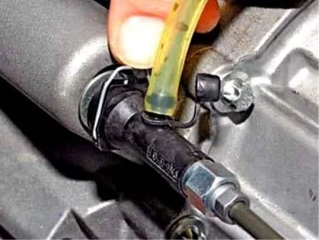
Press the spring-loaded clamp on the end of the hose.
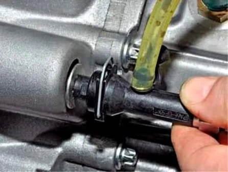
Move the adapter tube tip 4–6 mm.
This will force some of the brake fluid and air into the container.
Air bubbles are clearly visible in the container with the fluid.
After the fluid stops flowing into the container, push the tube tip onto the adapter until it stops.
After this, the assistant can release the clutch pedal.
Repeat this operation until air bubbles stop escaping from the hose.
Remove the hose and put the protective cap on the fitting.
When bleeding Check the fluid level in the reservoir and top up if necessary.
Possible Clutch Malfunctions and Troubleshooting Methods
Cause of Malfunction (Remedy)
Incomplete Clutch Disengagement (Clutch Drags):
- - Reduced clutch pedal travel - Repair the clutch release drive
- - Warping of the driven disc (axial runout) - Replace the driven disc
- - Uneven surfaces of the driven disc friction linings - Replace the driven disc
- - Loose rivets or broken friction linings of the driven disc - Replace the driven disc
- - Seizure of the driven disc hub on the splines of the transmission input shaft - Clean the splines, coat with LSC-15 grease. If the cause of seizure is crushed or worn splines, replace the input shaft or driven disk.
- - Air entering the hydraulic system - Bleed the system.
- - Fluid leaking from the clutch release master or slave cylinder - Replace the master or slave cylinder.
- - Loose pressure spring mounting rivets - Replace the clutch housing with the pressure plate assembly.
- - Distortion or warping of the pressure plate - Replace the clutch housing with the pressure plate assembly.
Incomplete clutch engagement (clutch slips):
- - Increased wear or burning of the friction linings of the driven disk - Replace the driven disk assembly.
- - Damage or seizure of the drive Clutch release - Troubleshoot the problem
Jerking during clutch operation:
- - The driven disk hub is sticking on the input shaft splines - Clean the splines, lubricate with graphite grease
- - Broken or reduced elasticity of the driven disk damper springs - Replace the driven disk
- - Sticking in the clutch release drive mechanism - Replace deformed parts
- - Increased wear of the driven disk friction linings - Replace the driven disk
- - Loose rivets of the driven disk friction linings - Replace the driven disk
- - Damaged basket - Replace the clutch basket
Increased noise when disengaging Clutch:
- - Worn, damaged, or leaking clutch release bearing - Replace bearing
Increased noise when engaging the clutch:
- - Broken plates connecting the pressure plate to the housing - Replace the clutch pressure plate
Clutch slippage can be easily detected by the tachometer.
If, while driving, when you press the gas pedal sharply, the RPMs rise sharply, then drop slightly and the car begins to accelerate, the clutch needs repair.


