


The rear suspensions of a car differ in design depending on the model.
In this article we shall examine the rear suspension of a 2WD and a 4WD car.
Rear suspension of a 4x2 car
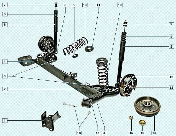
The rear suspension is semi-independent, with an elastic beam, spring type, with double-acting telescopic shock absorbers.
The beam is of U-shaped section with longitudinal arms welded to it.
The beam is rigid in bending, works in torsion, acting as a torsion bar.
This allows the rear axle wheels to move in the vertical plane independently of each other within certain limits.
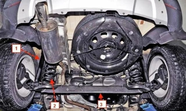
This suspension design brings it close to an independent suspension in terms of comfort, but it is cheaper and simpler to manufacture.
Brackets for supporting the springs are welded to the beam and arms.
To improve lateral stability and reduce roll angles, an anti-roll bar is installed inside the beam, the ends of which are welded to the arm reinforcements.
The anti-roll bar is a tube — of circular section at the ends and oval in the middle part.
Flanges for securing the rear wheel axles and brake mechanism backplates are welded to the suspension arms.
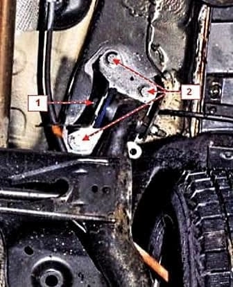
At the front, the arms are provided with welded bushes with rubber bushes pressed into them, which are intended for the articulated connection of the suspension arms to the body.
The outer race of the rubber bush is plastic, and the inner one is metal.
The rubber mass of the bush, vulcanised to the races, is asymmetrical in section.
Therefore, when pressing the bush into the arm, it must be strictly oriented.
The elastic elements of the suspension are coil springs.
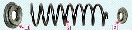
The spring rests through rubber pads: at the bottom — on the arm bracket and at the top — on the support welded to the body side member.
The pads prevent the transmission of high-frequency suspension vibrations to the body.
By preventing metal-to-metal contact, the pads also eliminate knocking and squeaking.
The lower coil of the spring has a smaller diameter.
Rear suspension springs are divided into classes by stiffness.
The spring class is marked with paint. Springs of the same class must be installed on the right and left sides of the car.
When replacing, it is recommended to install springs of the same class as those installed on the car.
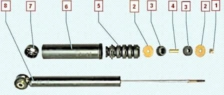
A rubber-metal joint is pressed into the lower eye of the shock absorber, through the central sleeve of which a bolt passes, connecting the shock absorber to the suspension arm.
The shock absorber rod is secured to the body through two rubber cushions (one below the support, the other above) and two metal washers.
Between the cushions on the shock absorber rod there is a spacer sleeve which prevents the cushions from deforming too much when tightening the rod nut.
A compression travel buffer is installed on the shock absorber rod, to which the cover is attached.
The buffer serves to limit the upward travel of the wheel.
It prevents deformation and breakage of suspension elements, and also eliminates the transmission of shock loads to the body.
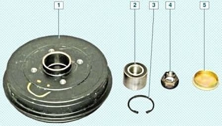
The rear wheel bearings are double-row.
The role of the rear wheel hub is performed by the brake drum, in the bore of which the outer bearing race is installed with an interference fit.
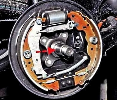
The inner bearing races are installed on the rear wheel stub axle (shaft) — with a small clearance.
In the drum the bearing is secured by a circlip.
During operation the bearing does not require replenishment of lubricant.
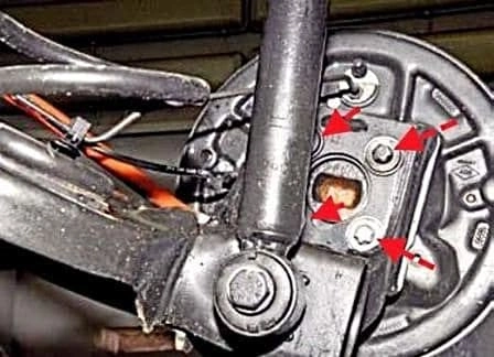
The rear wheel alignment angles are set by design by the beam geometry and are not adjustable in operation.
The angles can only be checked on a special test bench and compared with the control values.
If the values of the rear wheel alignment angles do not correspond to the control values, it is necessary to check the condition of the rear suspension elements.
Possible faults of the rear suspension of a 4x2 car
Noise and knocking in the suspension while the car is moving:
- Faulty shock absorber — replace the shock absorber
- Loosening of the shock absorber attachment or wear of the shock absorber eye bush — tighten the bolt with the nut of the lower shock absorber attachment or replace the bushes
- Wear of the rubber bushes of the longitudinal suspension arms — replace the rubber bushes
- Sagging or breakage of the spring — replace the spring
- Failure of the wheel hub bearing — replace the bearing
Deviation of the car from straight-line motion:
- Unequal air pressure in the tyres — set normal pressure in the tyres
- The tyres have different wear or tread pattern — replace the tyres
- Camber angle disturbed — eliminate the cause of the camber angle disturbance
- Sagging or breakage of one of the springs — replace the spring
- Deformation of the longitudinal arms — replace the rubber bushes
Increased or excessive tyre tread wear:
- Air pressure in the tyres does not correspond to the norm — set normal pressure
- Wheel alignment parameters disturbed — eliminate the causes of the wheel alignment parameters disturbance
- Overloading of the car — do not allow overloading of the car
- Wheel balancing disturbance — balance the wheels
Rear suspension of a 4x4 car
The rear suspension is independent, multi-link, with cylindrical coil springs and telescopic shock absorber struts serving to damp oscillations, absorb jolts and impacts acting on the car body through its wheels.
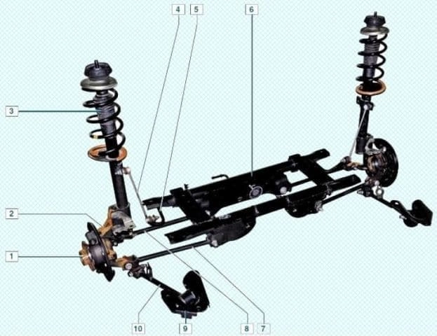
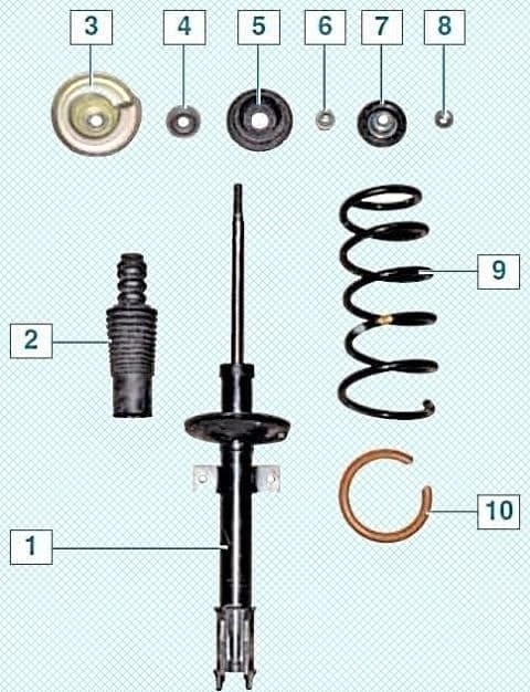
The shock absorber struts include elastic elements — springs, which prevent the wheels from lifting off the road, ensuring constant contact with the road.
The strut shock absorbers prevent body oscillations, which accordingly affects the safety and comfort of driving.
The shock absorber strut is secured at the bottom to the steering knuckle with two bolts with nuts, and the upper strut support is secured to the body with a nut.
The right and left shock absorber struts are interchangeable.
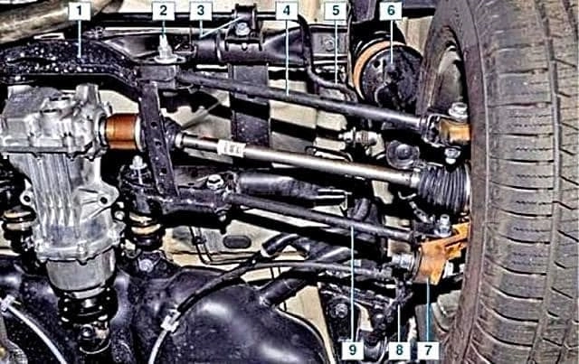
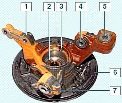
The steering knuckle is connected through rubber bushes by two transverse arms to the rear suspension subframe and by one longitudinal arm — to the bracket secured on the body.
The braking and traction forces during the movement of the car are absorbed by the longitudinal arms, and forces in the direction perpendicular to the longitudinal axis of the car — by the transverse arms of the suspension.
The left and right steering knuckles of the rear suspension are not interchangeable.
A double-row angular-contact ball bearing of closed type is installed in the steering knuckle, secured in the knuckle by a circlip.
The wheel hub is installed with an interference fit in the inner bearing races.
The inner bearing races are tightened (through the hub) by a nut on the shank of the outer joint body of the wheel drive.
In operation the bearing is not adjustable and does not require replenishment of lubricant.
The wheel hub securing nuts are identical, with right-hand thread.
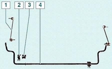
To improve lateral stability and reduce body roll angles, an anti-roll bar is installed.
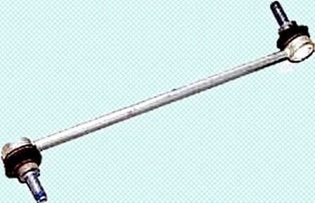
The ends of the anti-roll bar are connected through links with ball joints to the shock absorber struts.
The anti-roll bar links are interchangeable.
The anti-roll bar is secured with two clamps through split rubber bushes to the rear suspension subframe.
The bar is made of spring steel.
Of the rear wheel alignment angles, only their toe-in is adjustable.
The rear transverse suspension arm is connected to the subframe by a bolt having an eccentric collar and an eccentric washer.
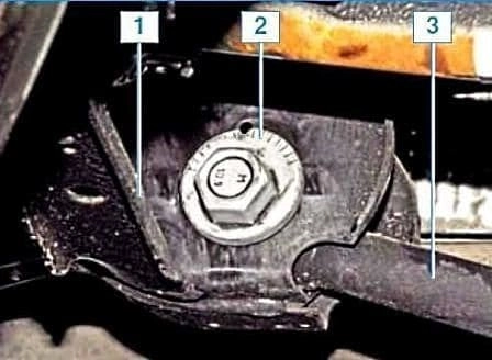
By turning this bolt the wheel toe-in is adjusted.
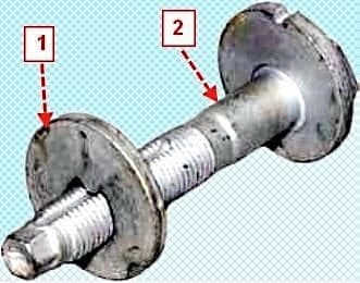
When the bolt with the washer is turned, its position in the subframe hole changes: when the bolt is displaced towards the longitudinal axis of the car, the reach of the rear transverse arm decreases and, consequently, the wheel toe-in angle decreases; when the bolt is displaced away from the axis — the angle increases.
The wheel camber angle is set by design by the suspension geometry and is not adjustable in operation.
The angle can only be checked on a special test bench and compared with the control values.
If the values of the angles do not correspond to the control values, it is necessary to check the condition of the rear suspension elements.
Possible faults of the rear suspension of a 4x4 car
Noise and knocking in the suspension while the car is moving:
- Faulty shock absorber — replace the shock absorber
- Loosening of the shock absorber strut attachment or wear of the upper strut attachment cushions — tighten the upper shock absorber strut attachment or replace the cushions
- Wear of the rubber bushes of the longitudinal suspension arms — replace the rubber bushes
- Sagging or breakage of the spring — replace the spring
- Failure of the rear wheel hub bearing — replace the bearing
Deviation of the car from straight-line motion:
- Unequal pressure in the tyres — set normal pressure in the tyres
- The tyres have different wear or tread pattern — replace the tyres
- Camber angle disturbed — eliminate the cause of the camber angle disturbance
- Sagging or breakage of one of the springs — replace the spring
- Deformation of the longitudinal arms — replace the rear suspension beam
- Wear of the rubber bushes of the longitudinal arms — replace the rubber bushes
Increased or uneven tyre tread wear:
- Air pressure in the tyres does not correspond to the norm — set normal pressure
- Wheel alignment parameters disturbed — eliminate the causes of the wheel alignment parameters disturbance
- Overloading of the car — do not allow overloading of the car
- Wheel balancing disturbance — balance the wheels
Pay attention to the exhaust system.
Extraneous knocking noises emitted by it are often mistaken for knocking in the rear suspension.
The use of non-standard parts or breakage of silencer suspension elements can cause severe knocking, especially when revving the engine.
To check, stop the engine, inspect the exhaust system, check the reliability of the attachment and the silencer suspension.
Grasping the end of the exhaust pipe, rock the silencer up and down and from side to side — there should be no knocking.


