After removing the cylinder head, we disassemble it and defect.
Removing the cylinder head was discussed in the article - "Removing the cylinder head from the engine".
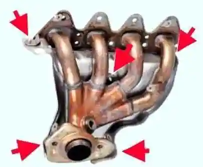
Remove the lower exhaust manifold heat shield (Figure 1).
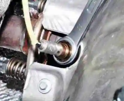
We pass the 22 spanner through the wire of the lambda probe sensor and unscrew it.
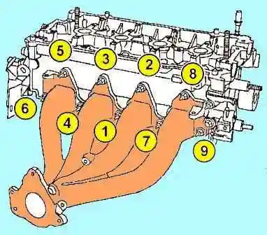
We unscrew the fastening of the upper heat shield and remove it (Fig. 3 shows the screen with the cylinder head installed).
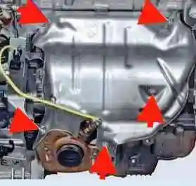
Remove the exhaust manifold (Figure 4).
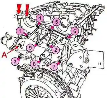
Unscrew the thermostat block from the cylinder head and remove it (Figure 5).
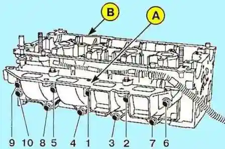
Remove the lining of the nozzle bodies (see Fig. 6).
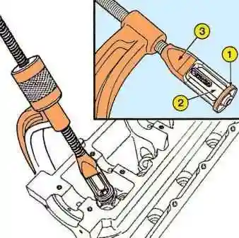
Compress the valve springs with tool Mot1502. The valve spring plate must fit into the bore (1) of the pressure sleeve (3) of tool Mot1502. (see fig. 7).
For correct compression of the valve springs, the tool plunger (2) must be centered on the valve stem.
Remove cotters, valve spring caps, valve springs, valves and valve stem seals using Mot1335 pliers.
Removing the exhaust tappet
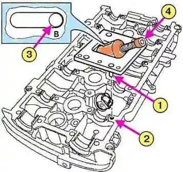
We bring the pin (3) of tool Mot1669 to the stop (B) at the end of the guide groove by unscrewing the screw (4) (see fig. 8).
Install tool Mot1669 on the cylinder head, correctly inserting the guide pin (1) into the hole (2) of the cylinder head cover (see fig. 8).
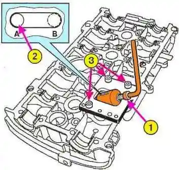
We fix the tool Mot1669 on the cylinder head cover with three bolts (see 3, fig. 9).
Tighten the screw (1) until the pin (2) rests at point (A) at the end of the guide slot.
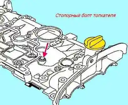
We turn out the locking bolt of the pusher (see the arrow, Fig. 10).
Unscrew the screw (1) until the pin (2) comes to rest at point (B) at the end of the guide slot (see fig. 9).
Remove tool Mot1669 from the cylinder head cover.
Remove the pusher and spring.
Install push exhaust valves
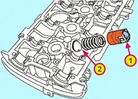
Install the spring and pushrod by aligning the groove (1) of the pushrod with the hole (2) in the cylinder head cover (see fig. 11).
- - bring the pin (3) of tool Mot1669 to the stop at the end of the guide groove by unscrewing the screw (4) (see fig. 8).
- - Install tool Mot1669 on the cylinder head, correctly inserting the dowel pin (1) into the hole (2) of the cylinder head cover (see fig. 8).
- - Fix tool Mot1669 to the cylinder head cover with three bolts (see 3, fig. 9).
- - Turn the screw (1) until the pin (2) is brought to a stop at point (A) at the end of the guide groove
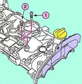
- - Screw the hex head bolt of tool Mot1669 into the cylinder head cover to block the pushrod (see arrow, fig. 12).
- - Unscrew the screw (1) until the pin (2) is brought to a stop at point (B) at the end of the guide groove (see fig. 9).
- - Remove tool Mot1669 from the cylinder head cover.
The cylinder head is assembled in the reverse order, after detection and repairof the head cylinders.


