We discussed the removal of the cylinder head in article. In this article, we will look at the disassembly and assembly of the cylinder head.
During the disassembly of the cylinder head, the parts must be marked and folded in order.
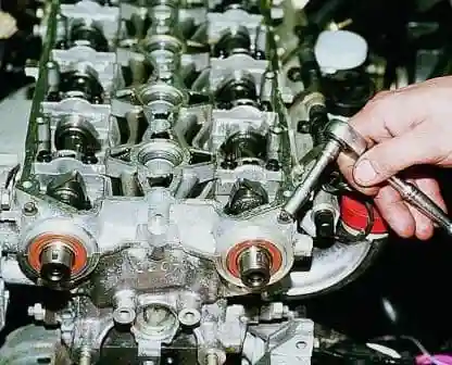
With a head of 8, we unscrew 20 bolts securing the camshaft bearing housing
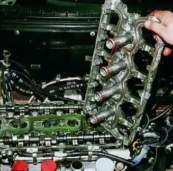
Remove the camshaft bearing housing.
Remove the spark plug guide tubes from the housing
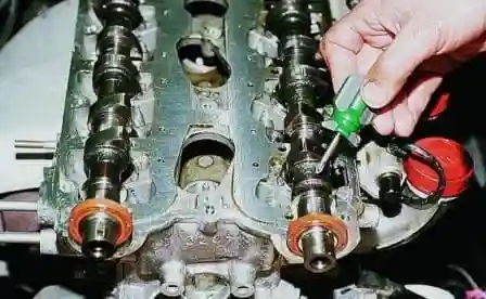
A belt is made near the first neck on the intake camshaft
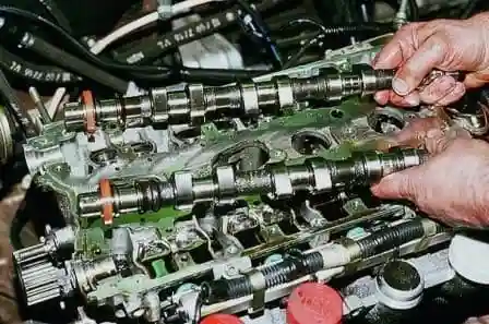
Remove the camshafts with oil seals
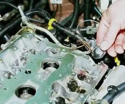
Removing the two camshaft end caps
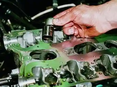
Using a magnet, we remove the hydraulic pushers from the sockets and put them in order
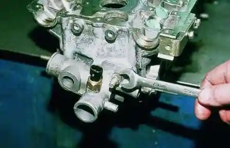
We unscrew the two nuts securing the cooling system pipe with a 13 wrench
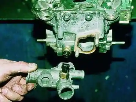
Remove the pipe
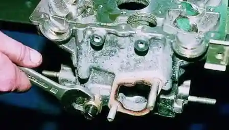
We unscrew the 21 coolant temperature sensor with a key
We put a wooden block under the valve plates.
Install the device for cracking the valves.
We install the thrust pad of the dryer on the valve spring plate, and we wind the hook lever behind the head of the bolt screwed into the hole in the cylinder head, designed to fasten the bearing housing.
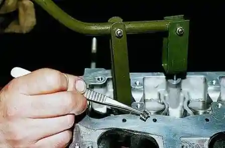
We press on the lever and compress the valve spring. Remove two valve crackers with tweezers
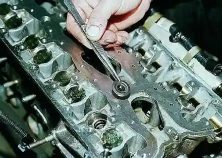
Removing the spring plate
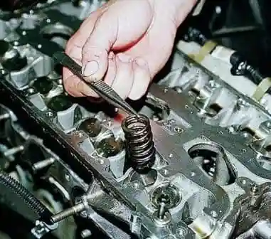
Remove the spring
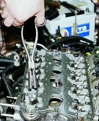
We use special pliers to remove the oil seals
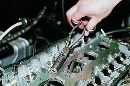
Remove the valve seals from the bushings
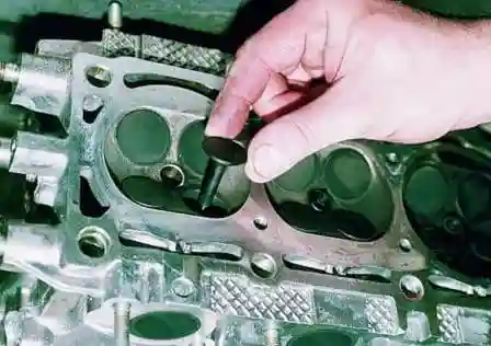
Remove the valves from the cylinder head guide bushings and put them in order
Check the flatness of the surface adjacent to the cylinder block.
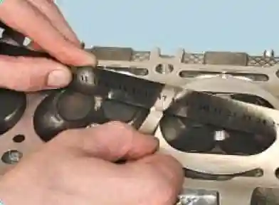
To do this, place the ruler with an edge on the surface of the head, first in the middle along, and then diagonally, and measure the gap between the surface of the head and the ruler with a feeler gauge.
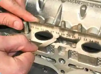
If the gap is greater than 0.1 mm, the mating surface can be sanded.
Similarly, check the flatness of the mating surfaces of the block head under the intake manifold
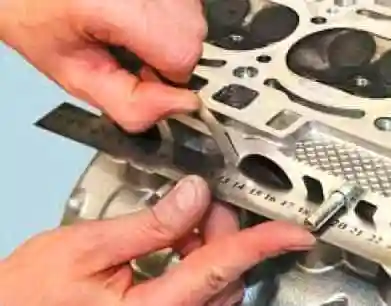
Check flatness under the collector.
The non-flatness of these surfaces should not exceed 0.1 mm
To check the tightness of the block head, plug the hole in the head under the thermostat socket.
This can be done, for example, by installing a blank pad of thick cardboard under the socket and tightening its fastening nuts.
Reinstall the coolant temperature sensor if it was removed.
Clean the valve from carbon deposits.
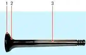
Check the condition of the valve visually.
Replace the valve if there are deep risks on the working chamfer 1, cracks, deformation of the stem 3, warping of the valve disc 2, traces of burnout.
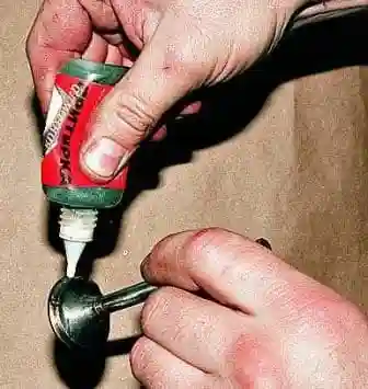
Shallow risks and scratches on the working chamfer of the valve can be removed by lapping the valves.
To do this, apply a continuous thin layer of lapping paste to the valve chamfer.
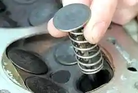
We put a pre-selected spring on the valve stem and insert the valve into the guide sleeve from the side of the combustion chamber.
We apply graphite grease to the valve stem itself so that the lapping paste does not get on the surface of the valve sleeve.
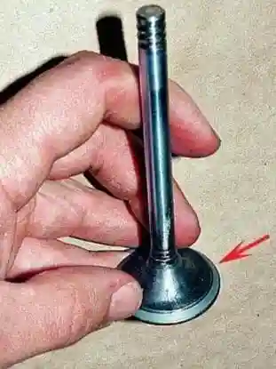
We put a valve lapping tool or a reversible drill with a hose tip to connect to the valve on the valve stem.
Turning on the drill at the minimum speed (in reverse mode) or rotating the device (in the case of manual lapping) alternately in both directions by half a turn, lap the valve, periodically pressing it against the seat, then loosening the pressing force.
An external sign of satisfactory lapping is a solid matte gray color of the valve face
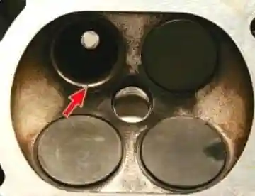
The valve seat should also have a solid gray stripe
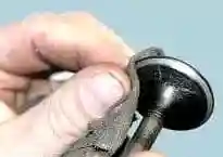
After lapping, carefully wipe the valve and valve seat from the lapping paste
Check the tightness of the valve by installing it with springs and crackers in the head.
Then put the head with the combustion chambers up, plug the spark plug hole and pour kerosene into the combustion chamber.
If kerosene does not seep into the channel of the block head within 3 minutes, the valve is tight.
In order to check the block head for cracks, you need to bring a hose for supplying compressed air to one of the holes in the cooling jacket.
Plug all holes in the head with wooden plugs.
Immerse the head in a bath of water and apply compressed air at a pressure of 1.5 atm.
In places where there are cracks, air bubbles will come out.
Inspect the valve lifters.
If there are scratches or other defects, replace the hydraulic pushers.
Measure the outer diameters of the tappets, replace the worn tappets.
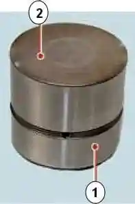
On working surfaces 2 there should be no scuffs, nicks, scratches, signs of stepped or uneven wear, metal rubbing.
Hydraulic tappets with such defects must be replaced.
On surfaces 2, concentric run-in marks with camshaft cams are allowed.
Check clearances between guide bushings and valves.
Clearance is calculated as the difference between the diameter of the hole in the sleeve and the diameter of the valve stem.
Gaps between valve and guide sleeve, mm:
- - nominal for inlet and outlet valves - 0.018-0.047
- - maximum allowable for intake and exhaust valves - 0.3
If the gap has not reached the maximum allowable, you can try to eliminate it by replacing the valve.
If this fails, or if the gap exceeds the limit, replace the guide bushing.
To do this, press out the defective bushing from the side of the combustion chamber with a mandrel, having previously measured the height of the protrusion of the upper part of the bushing above the surface of the block head.
Cool the new bushing with, for example, carbon dioxide, lubricate it with oil, insert it into a special mandrel and press it in from the camshaft side so that the protrusion of the upper part of the bushing corresponds to the measured value.
Ream the hole in the bushing using a reamer to 7.0 - 7.015 mm for the intake and exhaust valves.
Cylinder head assembly
We assemble the head in the reverse order, taking into account the following:
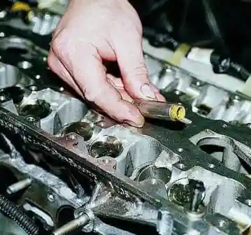
We use a special mandrel to press oil deflectors
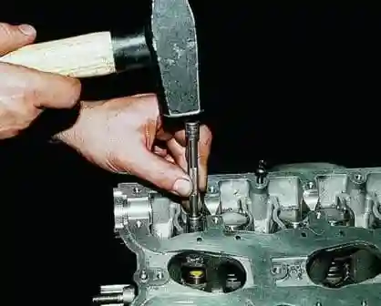
Lubricate the new valve stem seal and press it onto the valve guide
Install the block head on the engine - ( read the article on installing the cylinder head)

Installing valve lifters
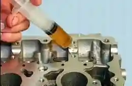
Lubricating the camshaft bearings and hydraulic tappets
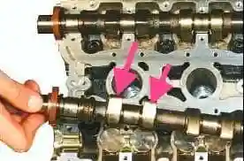
We install the camshafts in the head supports so that the cams of the 1st cylinder are directed away from the valve lifters
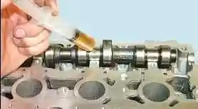
Lubricate the camshaft journals with engine oil
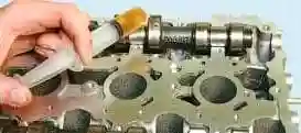
Lubricating the camshaft cams
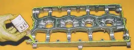
We apply sealant to the surface of the bearing housing
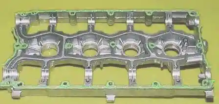
Points for applying sealant to the bearing housing
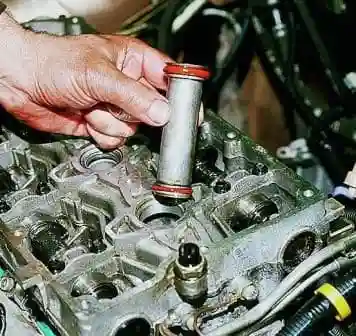
We install the bearing housing and tighten the fastening bolts evenly crosswise
Lubricating the O-rings of the guide pipes with engine oil, install the pipes
On the other side of the cylinder head, we press in the plugs.


