


The crankcase ventilation system ensures the removal of crankcase gases.
The crankcase gases pass through the extraction hose into the oil separator located on the cylinder block.
The hoses of the first and second circuits are two hoses (one of small diameter, the other of large diameter), through which the crankcase gases, after passing through the oil separator, are supplied to the receiver and then to the combustion chamber.
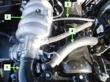
The first circuit has a calibrated orifice — a jet 1.7 mm in diameter.
The jet is located in the first circuit hose (small diameter hose), on the side connected to the oil separator union.
The first circuit hose runs from the oil separator to the receiver.
The second circuit hose (larger diameter hose) runs from the oil separator to the intake pipe hose.
At idle, all crankcase gases are supplied through the first circuit jet (small diameter hose).
In this mode, a high vacuum is created in the intake pipe, and the crankcase gases are effectively drawn into the space downstream of the throttle.
The jet limits the volume of gases drawn off so that engine operation at idle is not disturbed.
In load modes, when the throttle valve is partially or fully open, a small amount of crankcase gases passes through the first circuit jet.
In this case, their main volume passes through the second circuit (large diameter hose) into the intake pipe hose before the throttle connection and is then burned in the combustion chamber.
If the 1.7 mm jet is missing, the engine control system (ECM) erroneously determines an overestimated value of the blow-by through the throttle valve (the nominal value determined by the manufacturer is 3–5 kg/h), which leads to instability of the idle speed.
Cleaning the crankcase ventilation system
Over time, resinous deposits from the crankcase gases accumulate in the engine crankcase ventilation system, hindering the removal of these gases into the engine cylinders for combustion.
Because of this, the gas pressure inside the engine increases, and oil leaks appear through the seals.
To avoid this, periodically clean and wash the system.
Clean the crankcase ventilation system before each oil change.
You will need: a screwdriver, a «13» spanner, kerosene for washing, clean rags, a container for washing the parts.
Note: The oil separator fastening nut is difficult to access without a special tubular spanner. If you do not have such a spanner, clean the oil separator without removing it from the engine.
Caution! If, when cleaning the oil separator, a large amount of kerosene has entered the engine crankcase, change the oil in the crankcase.
Procedure for cleaning the crankcase ventilation system:
- Remove the high-tension lead tips from the spark plugs.
- Remove the oil level dipstick from the guide tube.
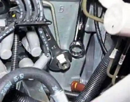
- Unscrew from the cylinder block hole the union of the oil supply pipe to the hydraulic tensioner of the timing drive chain and unscrew the two bolts fastening the pipe holders.
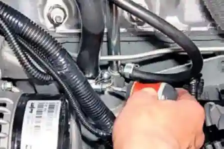
- With a screwdriver, loosen the clamp fastening the main circuit hose of the crankcase ventilation.
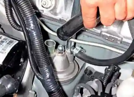
- Remove the hose from the union of the oil separator cover.
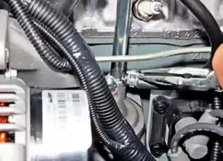
- Using pliers, loosen the clamp fastening the idle circuit hose of the crankcase ventilation.
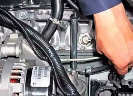
- Remove the hose from the union of the dipstick guide tube.
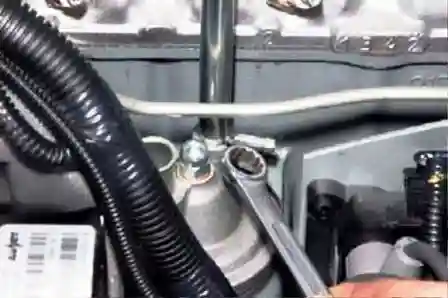
- With a 13 box spanner, unscrew the cap nut fastening the oil separator cover.
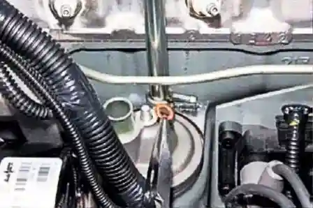
- Remove the copper sealing washer.
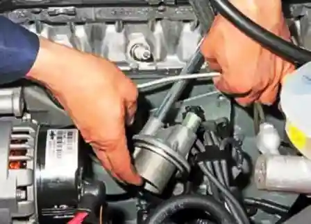
- Remove the oil separator cover, bringing it out between the oil supply pipe to the hydraulic tensioner and the wall of the cylinder block. The joint between the cover and the cylinder block is sealed with a paronite gasket.
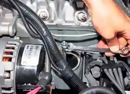
- Screw two M8 nuts onto the oil separator stud.
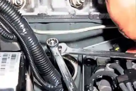
- Lock the nuts against each other with two 13 spanners.
- Unscrew the stud by the lower nut with a 13 spanner.
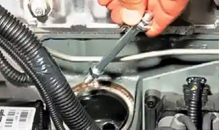
- Remove the stud from the oil separator.
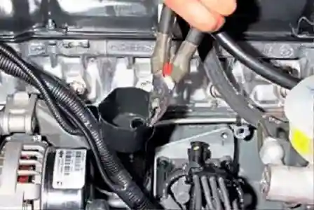
- Grip the edge of the oil separator with pliers.
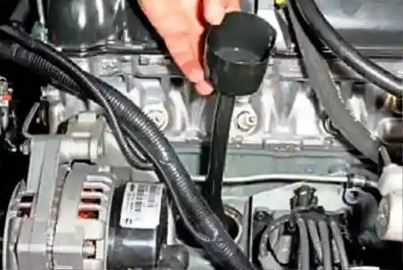
- Remove the oil separator from its seat in the cylinder block.
- Wash the oil separator parts with petrol or kerosene.
- Install the parts in the reverse order.
- Also wash the hoses of the ventilation circuits.


