
The fuel supply system filters the fuel and distributes it evenly among the engine cylinders in metered portions at strictly defined moments
The engine uses a split-type fuel supply system consisting of a fuel tank, low-pressure fuel lines, coarse and fine fuel filters, fuel priming and fuel pumps, a high-pressure fuel pump (HPFP), high-pressure fuel lines, injectors, an electromagnetic valve and pin plugs of the electric torch device (ETD).
The fuel tank, coarse fuel filter and fuel priming pump must be installed on the product on which the engine is used, all other elements of the fuel supply system are installed directly on the engine.
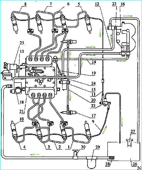
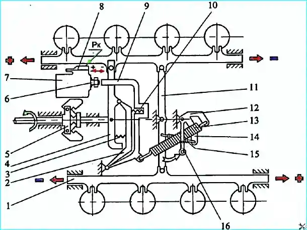
The diagram of the engine fuel supply system is shown in Figure 1.
Fuel from the fuel tank 26 through the coarse filter 29 and the fuel priming pump 30 is fed by the fuel priming pump 18, through the fuel pipe 13 to the fine filter 16.
From the fine filter, through the low-pressure fuel pipe 14, the fuel enters the high-pressure fuel pump 21, which, in accordance with the order of operation of the cylinders, distributes the fuel through the high-pressure fuel lines 1-8 to the injectors 10.
The injectors inject fuel into the combustion chambers.
Excess fuel, and along with it the air that has entered the system, is discharged into the fuel tank.
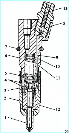
The nozzle model 273-20 or 273-50 of closed design, with five spray holes and hydraulic control of the nozzle needle lift is shown in Figure 2.
All the nozzle parts are assembled in the housing 6. The nozzle housing 1, inside which the needle 12 is located, is pressed to the lower end of the nozzle housing by nut 2 through spacer 3. The housing and the nozzle needle form a precision pair.
The angular fixation of the nozzle housing relative to the spacer and the spacer relative to the nozzle housing is carried out by pins 4.
The spring 11 exerts pressure on the upper end of the nozzle needle through rod 5.
The necessary tension of this spring is achieved by a set of adjusting washers 9, 10, installed between the spring and end of the internal cavity of the injector body.
Fuel is supplied to the injector under high pressure through the nipple 8 with a slotted filter 13 built into it, then through the channels of the body 6, spacer 3 and the body of the sprayer 1 - into the cavity between the body of the sprayer and the needle 12 and, lifting it, is injected into the engine cylinder.
Fuel leaking through the gap between the needle and the body of the sprayer is removed through the channels in the body of the injector and drained into the tank through the drain pipes 9 and 11 shown in Figure 1.
The injector is installed in the cylinder head, fixed with clamps, which are secured with a nut. The end of the nozzle nut is sealed against gas breakthrough with a corrugated copper gasket.
Sealing ring 7 (Figure 2) prevents dust and liquids from entering the cavity between the nozzle and the cylinder head.
It is strictly forbidden to install nozzles of other models
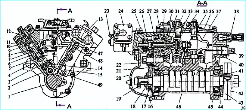
The high-pressure fuel pump (Figure 3) is designed to supply strictly dosed portions of fuel under high pressure to the engine cylinders at certain moments.
A high-pressure fuel pump with an all-mode regulator is installed on the engine of the automotive assembly.
High-pressure fuel pump characteristics
- Type 337
- Section operating order 8 - 4 - 5 - 7 - 3 - 6 - 2 - 1
- Direction of rotation of the camshaft (from the drive side) - right
- Plunger diameter, mm 11
- Plunger stroke, mm 13
- Nominal rotation speed of the camshaft, min-1 1100
Pump camshaft speed when the regulator control lever rests against the maximum speed limit bolt, min-1:
- - when the regulator completely switches off the fuel supply through the 1280 injector, no more than
- - at the beginning of switching off the regulator of the fuel supply through the 1140-1160 injector
Preliminary plunger stroke (from the beginning of its movement to the geometric start of injection in the eighth section), mm: 5.65±0.05
Alternation of the start of fuel supply by the angle of rotation of the camshaft, deg: - 0 - 45 - 90 - 135 - 180 - 225 - 270 - 315
Maximum force on the regulator control lever at nominal pump operating mode on a 50 mm shoulder, N (kgf) 127.5 (13)
Nominal cycle feed, mm³/cycle:
- - for fuel injection pump model 337-20.03 132-137
- - for fuel injection pump model 337-20.04 147-152
Eight sections are installed in the body 1 of the fuel injection pump (Figure 3), each of which consists of a body 6, a plunger sleeve 8, a plunger 7, a rotary sleeve 4, a discharge valve 11, the seat of which is pressed against the plunger sleeve 8 by a nipple 12.
The plunger performs a reciprocating motion under the action of the cam shaft 46 and the spring 3 of the pusher.
The pusher is fixed from turning in the housing by a cracker 14.
The cam shaft rotates in roller bearings 45 installed in steel rings pressed into the pump housing and pressed by covers.
The tension of the cam shaft bearings should be 0.05-0.15 mm and is adjusted by gaskets 44.
To change the fuel supply, the plunger 7 is rotated using the sleeve 4, connected through the axle of the driver to the rack 5 of the pump. The rack moves in guide bushings 40.
The holes for the guide bushings in the fuel injection pump housing on the drive side are closed with plugs 39.
On the opposite side of the pump there is a fuel supply corrector for the boost air pressure 24.
At the front end of the housing, where the fuel exits the pump, a bypass valve 38 is installed, which provides a pressure of 0.13-0.19 MPa (1.3-1.9 kgf/cm²) before the plunger inlet openings in operating modes.
The pump is lubricated by circulation, under pressure from the general lubrication system.
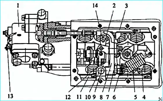
The fuel injection pump speed regulator (Figure 4) is all-mode, direct-acting, changes the amount of fuel supplied to the cylinders depending on the load, maintaining a given crankshaft speed.
The regulator is installed in the collapse of the fuel injection pump housing. The drive gear of the regulator 16 (Figure 39) is installed on the camshaft of the pump, the rotation of which is transmitted through a rubber 17.
The driven gear is made integral with the weight holder 28, rotating on two ball bearings.
When the holder rotates, the weights 31, swinging on the axes 29, diverge under the action of centrifugal forces and, through the thrust bearing 30, move the clutch 32 of the regulator, which, resting against the finger 34, in turn, moves the levers 2, 8 and 9 of the regulator (Figure 4), overcoming the force of the spring 5.
The lever 2 is connected via a pin to the right rack 3 of the fuel pump. The right rack is connected to the left rack 11 via rack lever 7.
The operation diagram of the speed governor is shown in Figure 5.
Governor control lever 16 is rigidly connected to lever 12. Governor spring 13 is connected to lever 12, and starting spring 15 is connected to levers 14 and 11.
During governor operation, the centrifugal forces of the weights are balanced by the force of spring 13.
As the crankshaft speed increases, the weights, overcoming the resistance of spring 13, move levers 2, 4 and 9, and with them the fuel injection pump rack - the fuel supply decreases.
As the crankshaft speed decreases, the centrifugal force of the weights decreases, and the levers with the fuel injection pump rack, under the action of the spring force, move in the opposite direction - the fuel supply and the crankshaft speed shaft increase.
When the regulator lever 9 rests on the bolt 6 and the crankshaft speed is less than 1800 min-1, the spring 10 of the direct corrector moves the pump racks (via levers 2 and 4) towards increasing the fuel supply, providing the required value of the maximum engine torque.
At a speed of less than 1400 min-1, the spring 3 of the reverse corrector moves the lever 4 with the racks towards decreasing the fuel supply, limiting the maximum smoke of the engine exhaust gases.
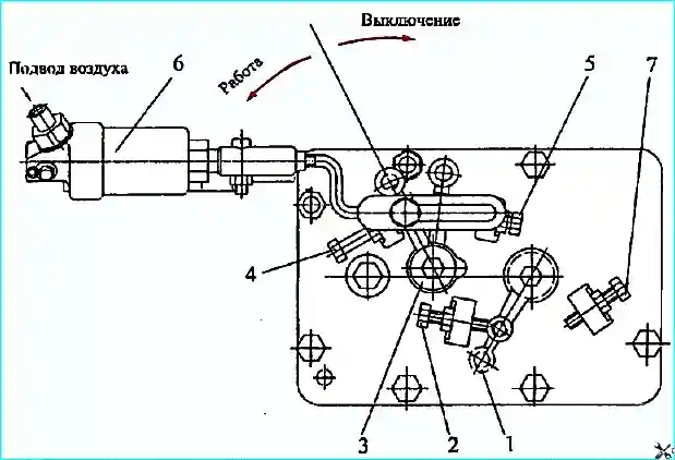
The fuel supply is stopped by turning the lever 3 (Figure 6) of the engine stop until it stops against the bolt 5.
In this case, the lever 3, having overcome the force of the spring of the lever 33 (Figure 3) and the spring 5 (Figure 4), through the pin 14 will turn the levers 2, 8 and 9, the racks will move until the fuel supply is completely stopped.
Checking and adjusting the high-pressure fuel pump, as well as replacing the plunger pairs, sealing rings of the high-pressure fuel pump sections must be carried out in a specialized workshop by a qualified specialist.
It is prohibited to install high-pressure fuel pumps of other models on engines 740.50-360 and 740.51-320 except for the above, in order to avoid engine failure!
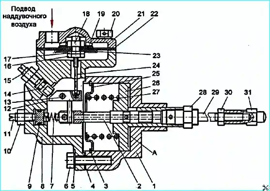
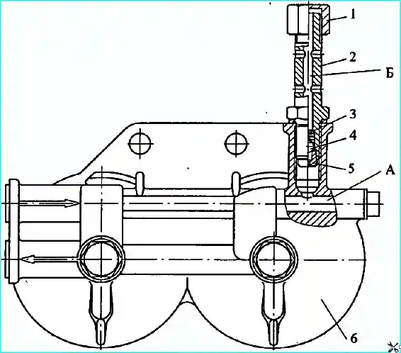
Boost air pressure corrector (Figure 7).
Boost air pressure corrector reduces fuel supply when boost air pressure drops below 40-45 kPa (0.4-0.45 kgf/cm²), thereby providing thermal protection for the engine and limiting exhaust smoke.
Piston 26 with spool 2 is installed in corrector body 1. Spring 27, fixed by plate 25 and ring 3, acts on the piston.
A spring is screwed into the piston and The stud 29 is locked with a nut 28 with a tip 31, which is the nominal stop in the regulator.
The tip is locked with a nut 30. A spring 7 acts on the spool 2, the pre-tension of which can be changed by the adjusting screw 11.
The membrane housing 8 is attached to the corrector body 1 through a gasket 4.
The membrane unit with the rod (parts 24,16,17,23, 22, 19,18) is installed in it. The membrane is clamped between the housing 8 and the cover 21.
In the housing of the membrane 8, on the axis of the lever 13, the corrector lever 12 is installed, the rotation of which is limited by the adjusting screw 15.
The fuel supply corrector is not direct acting: when the boost air pressure in the membrane cavity changes, the position of the spool changes, which, in turn, determines the position of the corrector piston.
Oil under pressure from the engine lubrication system is supplied to cavity "A" between the housing of the corrector 1 and the piston 26 through a threaded hole and a 0.7 mm nozzle in the housing of the corrector (not shown in the figure).
Under the action of this pressure, the piston, compressing the spring 27, moves to the left until the windows in the piston and spool open and the oil goes to drain.
In this case, a constant oil flow is established through corrector.
When the position of the spool changes, the piston moves after it (tracking system).
Air from the engine intake manifold is supplied to the membrane cavity through the threaded hole in the cover 21.
When the air pressure drops below 0.05 MPa (0.5 kgf/cm²), the force of the corrector spring 7 acting on the spool becomes greater than the force created by the pressure of the boost air on the membrane and transmitted through the membrane rod and the corrector lever also to the spool.
The spool moves to the right until a balance of the forces acting on it is achieved.
Following the spool, the piston with the pin 29 and the tip 31 moves to the right, moving the regulator lever 8 resting against it to the right (Figure 4).
Following the regulator lever, under the action of centrifugal forces of the loads, levers 9.2 and 7 move with the pump racks in the direction of decreasing the fuel supply.
Adjusting the corrector
The corrector has two external adjustments - screws 11 and 15 (Figure 7).
Screw 11 changes the preliminary tension of the corrector spring 7, thereby changing the start of the corrector operation.
If it is necessary to increase the value of the boost air pressure at which the corrector begins to operate, screw 11 is tightened, increasing the preliminary tension of the spring 7.
Screw 15 regulates the nominal cyclic fuel supply. When screw 15 is turned out, the fuel supply increases.
If it becomes necessary to remove the corrector, it is first necessary to measure the protrusion of the tip of stud 31 relative to the rear end of the fuel injection pump housing, and after installing the corrector in place, restore the size of this protrusion and lock the tip with nut 30.
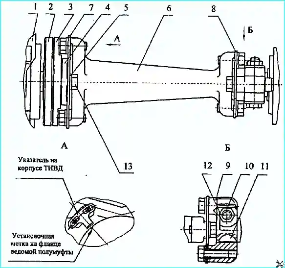
The fuel injection pump drive is shown in Figure 8. It consists of a fuel injection pump drive shaft 6 with packs of front 7 and rear 8 compensating plates, a driven half coupling 2, a flange of a driven half coupling 3, a centering flange 4, a leading half coupling 9 and centering bushings 5.
Each pack of compensating plates consists of 5 plates, each 0.5 mm thick.
All bolts in the fuel injection pump drive, except for the bolt pos. 10, must be of strength class R100 and tightened with a torque of 65-75 Nm (6.5-7.5 kgfm).
The tightening of all bolts must be checked with a torque wrench. Before installing the bolts, check for the presence of centering bushings.
Deformation (bending) of the front and rear compensating plates is not allowed. Bolt 10 of the drive half coupling should be tightened last to a torque of 78.4-84.3 Nm (8-8.6 kgfm).
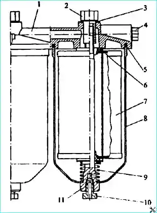
The fine fuel filter is shown in Figure 9. It is designed for the final cleaning of fuel from small particles before entering the high-pressure fuel pump.
The filter is installed at the highest point of the fuel supply system to collect and remove air into the tank together those with part of the fuel through the valve (Figure 10), installed on the bypass from the filter.
When replacing filter elements, it is necessary to strictly observe the rules for servicing the fuel supply system.
Do not allow contaminants to enter the system and use filter elements only of the following models 740.1117040-01, 740.1117040-02, 740.1117040-04.90
The valve is shown in Figure 10.
When the pressure in the fuel supply cavity "A" reaches 25-45 kPa (0.25-0.45 kgf/cm²), the ball 4 moves and the fuel flows from cavity "A" to cavity "B" through the valve jet 5.
The piston-type fuel priming pump 13 (Figure 3) is designed to supply fuel from the tank through the coarse and fine filters and the fuel priming pump to the inlet cavity of the high-pressure fuel pump.
The pump is installed on the rear cover of the regulator, its drive is carried out from the eccentric 19, located on the rear end of the camshaft of the high-pressure fuel pump.
The piston, piston spring, rod bushing 47 and pusher rod 48, inlet and outlet valves with springs.
Eccentric 19 through roller 49, pusher 15 and rod 48 imparts reciprocating motion to the piston of the fuel pump.
The pump operation diagram is shown in Figure 11. When pusher 9 is lowered, piston 1 moves downwards under the action of spring 4.
A vacuum is created in cavity "A" and inlet valve 2, compressing spring 3, passes fuel into cavity "A".
At the same time, the fuel located in the discharge cavity "B" is forced out into line "G", while valve 5 closes under the action of spring 6, preventing fuel from flowing from cavity "B" to cavity "A".
When piston 1 moves upward, the fuel filling cavity "A" enters cavity "B" under piston through discharge valve 5, while intake valve closes.
When pressure in discharge line increases, piston does not make full stroke following pusher, but remains in position, which is determined by balance of fuel pressure force on one side and spring force on the other.
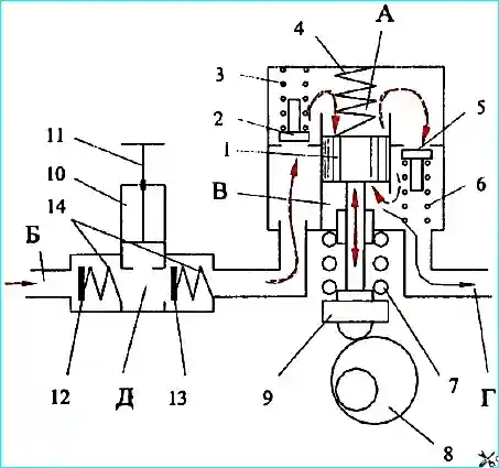
The fuel priming pump 10 (Figure 11) is a piston type and serves to fill the fuel system with fuel before starting the engine and to remove air from it.
The pump consists of a housing, piston, cylinder, inlet and delivery valves.
The fuel system should be pumped using the pump piston, having first unlocked it by turning it counterclockwise.
When piston 11 moves upward, a vacuum is created in the space beneath it. Inlet valve 12, compressing spring 14, opens and fuel enters cavity "D" of the pump.
When the piston moves down, the inlet valve closes and discharge valve 13 opens, fuel under pressure enters the discharge line, ensuring the removal of air from the engine fuel system through the fine fuel filter valve and the bypass valve of the high-pressure fuel pump.
After pumping the system, it is necessary to lower the piston and fix it by turning it clockwise.
In this case, the piston will be pressed against the end of the cylinder through the rubber gasket, sealing the suction cavity of the fuel priming pump.
It is not allowed to start the engine with an unfixed piston due to the possibility of air being sucked in through the piston seal.
Fuel lines are divided into low-pressure fuel lines - 0.4-2 MPa (4-20 kgf/cm²) and high pressure over 20 MPa (200 kgf/cm²).
Low pressure fuel lines are made of 10 mm steel pipe with soldered tips.
High pressure fuel lines of equal length (1=595 mm) are made of steel tubes with an internal diameter of 2+0.05 mm by fitting connecting cones with compression washers and union nuts at the ends for connection to the fuel injection pump and injector fittings.
To avoid damage from vibration, the fuel lines are secured with clamps to the intake manifolds.

")
")
")
")
")
")
")
")