All operations are conditionally shown on the removed engine.
Because the engine can be installed on different types of cars.
Remove the inlet pipe.
Remove the intake silencer.
Operations common to all vehicle configurations
Remove the accessory drive belt.
Remove the crankshaft pulley.
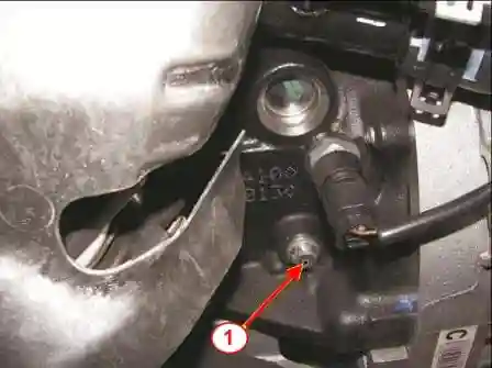
Remove plug 1, figure 1, holes for the TDC lock (replaceable head Torx E14, extension, ratchet wrench).
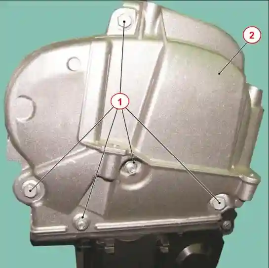
Unscrew the bolts and nuts 1, figure 2, fastening the upper timing cover (replaceable heads 13, ratchet wrench).
Remove the upper timing cover 2.
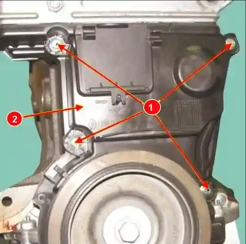
Unscrew the bolts 1, figure 3, fastening the lower timing cover (replaceable head 8, ratchet wrench).
Remove the lower timing cover 2.
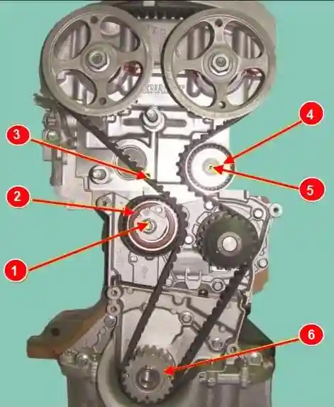
Loosen the tightening of the nut 1, Figure 4, fastening the tension roller axle (replaceable head 16, ratchet wrench).
Remove the bolt 5 securing the idler roller using a tool (tool Mot. 1368, interchangeable head Torx T50, ratchet wrench).
Remove the bypass roller 4.
Remove timing belt 3.
Unscrew nut 1 fastening the tension roller axle (replaceable head 16, ratchet wrench).
Remove the timing belt tensioner 2.
Remove the crankshaft 6 toothed pulley.
Attention. Parts that must be replaced:
- - timing belt;
- - timing belt tensioner;
- - bypass roller of the timing belt;
- - crankshaft pulley bolt;
- - inlet camshaft plug;
- - exhaust camshaft plug.
Attention. Before installing the crankshaft pulley, degrease the bearing surface of the pulley and the toe of the crankshaft.
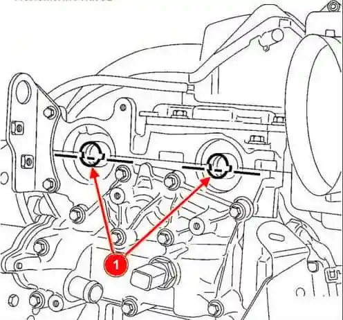
Locate the grooves of the camshafts 1, figure 5, horizontally and offset downwards from the axes of the shafts, if necessary, turning the camshafts using a tool (tool Mot. 1496, change head 16, extension, ratchet wrench).
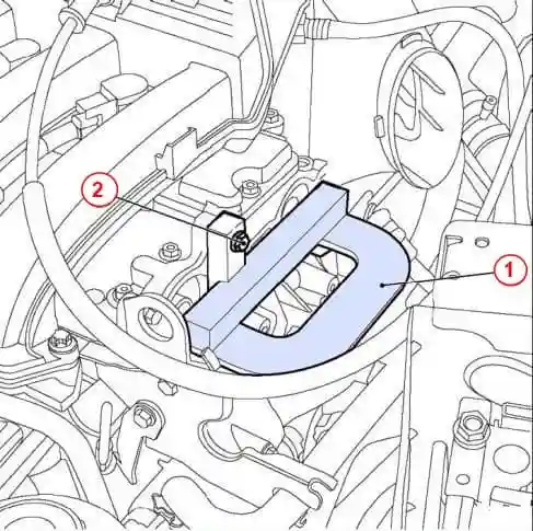
Install fixture 1, Figure 6, for setting the valve timing on the engine and secure with bolt 2 (tool Mot1496, interchangeable head 10, extension, knob).
Arrange the marks on the spokes of the camshaft pulleys vertically upwards.
Install a new tension pulley 2, Figure 4, of the timing belt, sliding its protrusion into the groove.
Wrap, without tightening, the nut 1 of the tension roller axle (replaceable head 16, ratchet wrench).
Set tooth crankshaft pulley 6.
Install a new timing belt 3.
Install a new idler 4 of the timing belt.
The tightening torque of the bolt 5 for fastening the timing belt bypass roller is 50 Nm (5.0 kgf.m) (Mot1368 tool, interchangeable head 16, ratchet wrench, torque wrench).
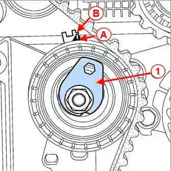
Use a 6 mm hexagon wrench to align the movable pointer (A), figure 7, with the notch (B) of the fixed pointer by turning the eccentric 1 clockwise.
Tighten the nut fastening the timing belt tension roller to a torque of 7 N.m (0.7 kgf.m) (replaceable head 16, torque wrench).
Install the bottom cover 2, figure 3, of the timing drive.
The tightening torque of the bolts 1 for fastening the lower cover of the timing drive is 12 Nm (1.2 kgf.m) (replaceable head 8, ratchet wrench, torque wrench).
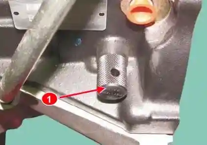
Install retainer 1, Figure 8, TDC on the cylinder block (TDC retainer Mot1489 or 67.7820-9701 L).
Install the crankshaft pulley.
Remove bolt 2, figure 6, fastening tool Mot. 1496 and remove tool 1 for setting the valve timing (replacement head 10, extension, knob).
Remove the TDC lock from the cylinder block (TDC lock Mot1489 or 67.7820-9701 L).
Checking the tension of the timing belt on the K4M engine
Turn the crankshaft two turns clockwise (when viewed from the timing side) and until the previously made marks (on the phase regulator pulley) align, install the TDC lock on the cylinder block.
Carefully bring the crankshaft to the stop in the lock (replaceable head 18, ratchet wrench).
Remove the TDC lock from the cylinder block (TDC lock Mot1489 or 67.7820-9701 L).
Make sure that the movable pointer A, figure 7, is against the notch B of the fixed pointer, if it is not:
- - unscrew the nut 1, figure 4, fastening the tension roller by no more than one turn, holding the movable pointer with a 6 mm hex wrench (replaceable head 16, ratchet wrench);
- - smoothly move the movable pointer to coincide with the notch by turning the eccentric clockwise.
Tighten the timing belt tensioning roller nut to 27 Nm (2.7 kgf.m) (replaceable head 16, torque wrench).
Checking the installation of the valve timing on the K4M engine
Before checking the valve timing, make sure that the movable pointer A, figure 7, the tension roller and the notch B of the fixed pointer are in the correct position.
Install retainer 1, Figure 8, TDC on the cylinder block (TDC retainer Mot1489 or 67.7820-9701 L).
Carefully bring the crankshaft to the stop in the lock (replaceable head 18, ratchet wrench).
Install (without force) fixture 1, figure 6, for setting the valve timing (grooves at the ends of the camshafts 1, figure 5, must be in a horizontal position and be shifted down from the shaft axes) (tool Mot1496).
If tool Mot. 1496 does not fall into place, then you need to re-install the valve timing and adjust the tension of the timing belt.
Remove tool Mot. 1496 for setting the valve timing.
Remove the TDC lock from the cylinder block (TDC lock Mot1489 or 67.7820-9701 L).
Install the window cover on the lower timing cover, making sure the pin fits into the notch.
Operations common to all vehicle configurations
Apply sealant to the threads of plug 1, Figure 1, the holes for the TDC retainer and tighten the plug. Plug tightening torque 20 N.m (2.0 kgf.m) (replaceable head Torx E14, extension, ratchet wrench, torque wrench).
- Install the right engine mount.
- Install the crankshaft pulley.
- Install the accessory drive belt.
- Install the inlet.
- Install the intake silencer.


