


Removal of the camshaft was covered in the article ‘How to dismantle the engine’.
Some car enthusiasts, when repairing the engine, pay little attention to the condition of the camshaft.
They focus mainly on the cylinder-piston group and the crankshaft.
Which adversely affects the further operation of the engine.
Particular attention should be given to the camshaft and its bearings.
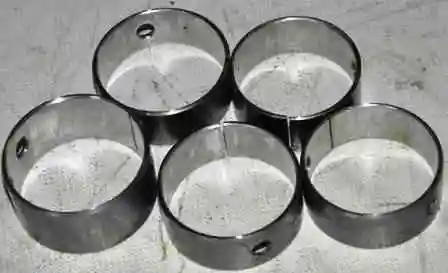
If the camshaft bushes are heavily worn, new bushes must be pressed in.
A new camshaft must be fitted.
Inspection and fault diagnosis of the camshaft
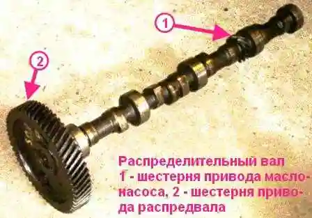
After removal, wash all parts in petrol, wipe them and dry them.
Inspect the camshaft.
If the journals, cams and oil pump drive gear show scoring, deep scratches, pitting, chipping or cracks, replace the camshaft.
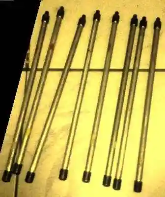
Inspect the pushrods. Replace any bent pushrods.
If the ends of the pushrods show signs of wear, scoring or pitting, replace the pushrods as well.
Note that the pushrod length of the mod. 402 engine is 283 mm, and that of the mod. 4021 engine is 287 mm.
Measure the diameters of the camshaft journals; the nominal journal diameters are given in the table.
Inspect the tappets.
If the working surfaces show signs of wear, pitting, scoring, etc., replace the tappets.
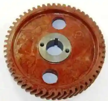
If the teeth of the camshaft gear are damaged or cracked, it must be replaced.
Measure the camshaft end float.
To do this, temporarily assemble the shaft with the gear, fit the spacer ring and thrust flange onto the front end of the camshaft, then press on the gear and tighten the gear securing bolt with its washer.
Tighten the bolt to a torque of 55–60 N·m (5.5–6.0 kgf·m).
Using a feeler gauge, measure the gap between the camshaft thrust flange and the gear hub; it should be within 0.1–0.2 mm.
The camshaft is fitted in the reverse order of removal.
Before fitting, lubricate the camshaft journals and cams, the tappets and the pushrods with engine oil.
After fitting, adjust the clearances in the valve train.
Nominal dimensions and fits of the mating parts of the camshaft of the mod. 402 engine
| Part name | Nominal diameter, mm | Mating part name | Nominal diameter, mm |
|---|---|---|---|
| First camshaft journal | 52.0−0.02 | Cylinder block | 52.0+0.075 52.0+0.05 |
| Second camshaft journal | 51.0−0.02 | Cylinder block | 51.0+0.075 51.0+0.05 |
| Third camshaft journal | 50.0−0.02 | Cylinder block | 50.0+0.05 |
| Fourth camshaft journal | 49.0−0.02 | Cylinder block | 49.0+0.075 49.0+0.05 |
| Fifth camshaft journal | 48.0−0.02 | Cylinder block | 48.0+0.075 48.0+0.05 |
| Gear | 28.0+0.023 | Camshaft | 28.0+0.023 28.0+0.002 |
| Valve tappet | 25.0−0.008 25.0−0.022 |
Cylinder block | 25.0+0.023 |
| Pushrod end | 8.75+0.03 8.75−0.02 |
Pushrod | 8.75+0.045 8.75−0.035 |
| Part name | Clearance, mm | Interference, mm | ||
|---|---|---|---|---|
| min | max | min | max | |
| First camshaft journal | 0.05 | 0.095 | — | — |
| Second camshaft journal | 0.05 | 0.095 | — | — |
| Third camshaft journal | 0.05 | 0.095 | — | — |
| Fourth camshaft journal | 0.05 | 0.095 | — | — |
| Fifth camshaft journal | 0.05 | 0.095 | — | — |
| Gear | — | 0.021 | — | 0.023 |
| Valve tappet | 0.015 | 0.038 | — | — |
| Pushrod end | — | — | 0.005 | 0.065 |