

We conventionally remove the cylinder head on the engine removed from the vehicle. Therefore, the preparation operations for cylinder head removal are not covered in this article.
Removal of the rocker cover
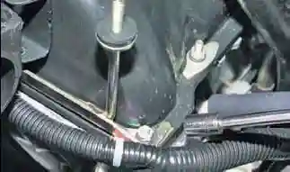
- Using a 10 mm socket or a box spanner, we unscrew the eight nuts securing the cylinder head cover.
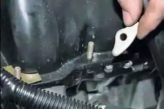
- We remove from the studs the engine shield mounting brackets, six clamping washers and the wiring harness holders.
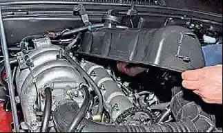
- We remove the rocker cover.
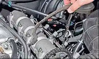
- We extract the cover gasket.
Setting TDC and removing the hydraulic tensioner
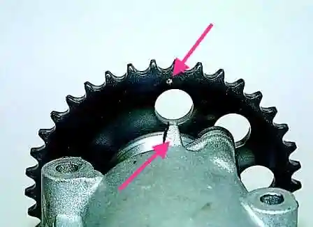
- We turn the crankshaft until the mark on the camshaft sprocket coincides with the mark on the camshaft bearing housing.
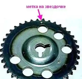
Removal of the hydraulic chain tensioner
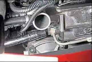
- Using a 13 mm socket, we unscrew the union of the oil supply pipe to the tensioner.
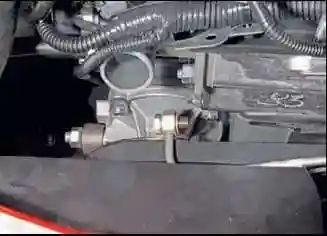
- We remove the copper washer from the union and withdraw the banjo bolt with its gasket.
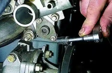
- Using a 10 mm socket, we unscrew the two nuts securing the tensioner to the cylinder head.
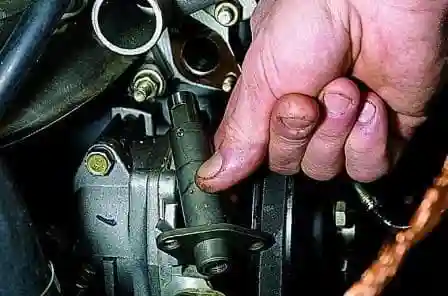
- We remove the tensioner and gasket.
Removal of the camshaft
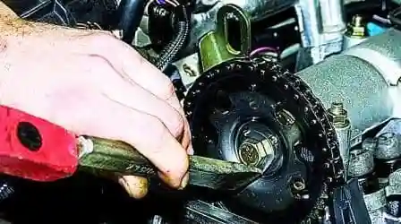
- We bend back the lock washer on the camshaft sprocket with a screwdriver or a chisel.
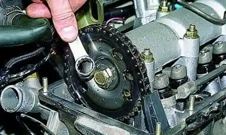
- Using a 17 mm box spanner, we unscrew the bolt securing the camshaft sprocket.
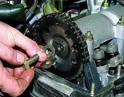
- We extract the bolt with the lock washer.
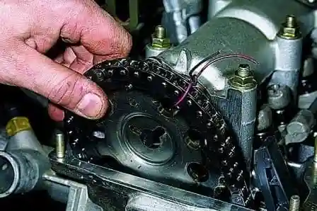
- We tie the chain to the sprocket and remove it together with the chain from the camshaft.
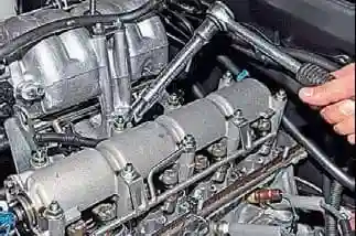
- Using a 13 mm socket, we evenly unscrew the nine nuts securing the camshaft bearing housing and the oil supply pipe to the hydraulic supports.
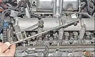
- We remove from the cylinder head studs the oil supply pipe to the hydraulic supports of the valve rockers.
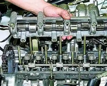
- We remove the camshaft together with the bearing housing.
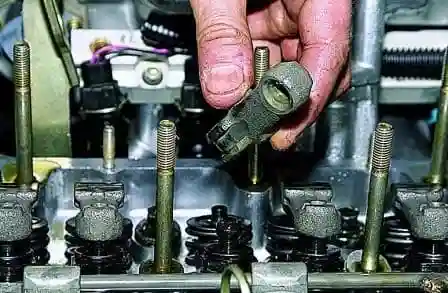
- We remove the valve rockers. The parts are marked or laid out in order.
Removal of the cylinder head
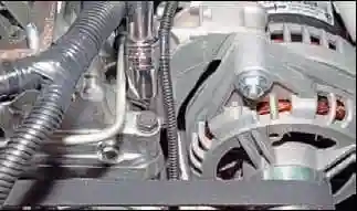
- Using a 13 mm socket, we unscrew the cylinder head mounting bolt located next to the alternator bracket.
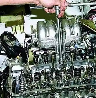
- Using an E16 socket, we unscrew the ten bolts securing the cylinder head to the cylinder block and withdraw the bolts.
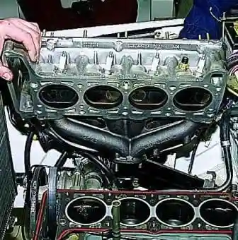
- We remove the cylinder head as an assembly with the thermostat, throttle body, receiver, injection rail and exhaust manifold.
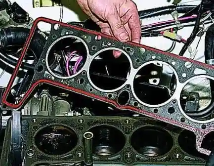
- We extract the gasket under the cylinder head.
We wash the cylinder head, inspect and verify the head.
Installation of the cylinder head
We fit the cylinder head in the reverse order.
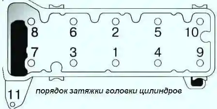
We tighten the cylinder head in four stages:
- 1st stage – tighten bolts 1–10 to a torque of 20 N·m (2.0 kgf·m);
- 2nd stage – tighten bolts 1–10 to a torque of 69.4–85.7 N·m (7.1–8.7 kgf·m), and bolt 11 to a torque of 31.4–39.1 N·m (3.2–4.60 kgf·m);
- 3rd stage – turn bolts 1–10 a further 90°;
- 4th stage – turn bolts 1–10 a further 90°.


