


The timing drive of the VAZ-2123 engine consists of sprockets, a chain, a guide shoe, a damper and a hydraulic chain tensioner.
The engine chain is single-strand, unlike the engines of previous models.
If, with a serviceable tensioner and its shoe, and with unworn drive sprockets, the chain tension cannot be restored, it means that the chain has stretched excessively and must be replaced. When the chain tensioner shoe wears, the tensioner's operating range becomes insufficient to restore the chain tension. In this case, replace the shoe.
The damper is located inside the front part of the cylinder head on the left and is secured to it externally by two bolts. If the damper is worn or damaged, resonance vibrations of the driving chain run may occur under certain engine operating conditions, which can lead to the chain jumping over the teeth of the camshaft sprocket and serious engine damage.
Of course, if the chain has stretched and needs replacing, it is desirable to replace all the drive components as well.
Removal of the chain and sprockets of the timing drive and oil pump
- We remove the cylinder head cover.
- We turn the crankshaft until the mark (recess) on the camshaft sprocket coincides with the mark on the camshaft bearing housing.
- We remove the crankshaft pulley.
- We detach the camshaft sprocket with the chain from the camshaft.
- We remove the chain from the sprocket.
The chain removal operations are shown on the engine removed from the vehicle.
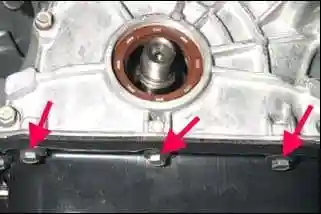
- We unscrew three bolts securing the sump to the camshaft drive cover.
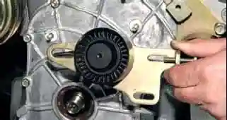
- We remove the bracket with the roller.
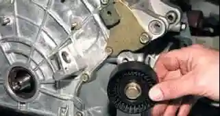
- We unscrew the bolt securing the support roller and remove it.
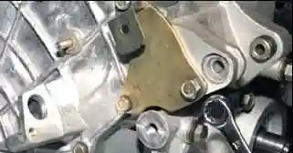
- We unscrew the bolt securing the plate to the alternator mounting bracket.
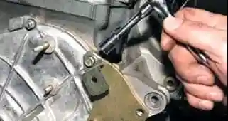
- Using a 10 mm spanner, we unscrew the upper bolt securing the plate.
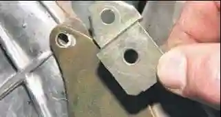
- We remove the wiring holder bracket of the crankshaft position sensor.
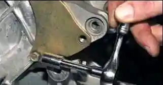
- Using a 10 mm spanner, we unscrew the lower bolt securing the plate.
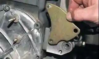
- We remove the plate.
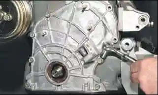
- Using a 10 mm spanner, we unscrew five bolts and two nuts securing the timing drive cover to the block.
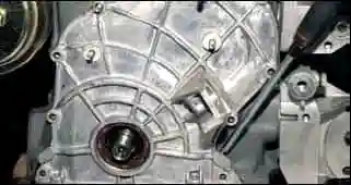
- We prise off the cover at its lug with a screwdriver.
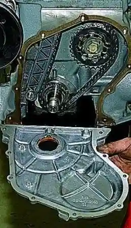
- We remove the cover.
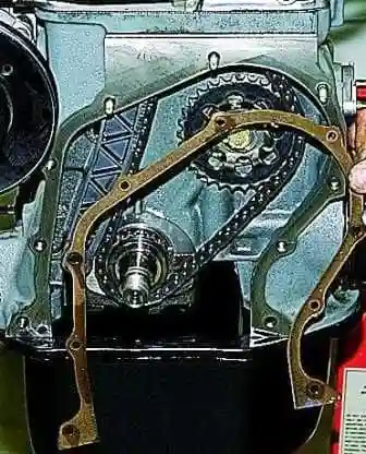
- We remove the cover gasket.
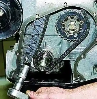
- Using a 17 mm socket, we unscrew the axis of the chain tensioner shoe.
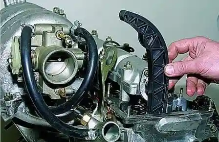
- We extract the chain shoe.
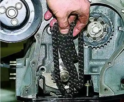
- We pull out the timing drive chain.
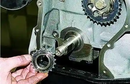
- We remove the sprocket from the front end of the crankshaft.
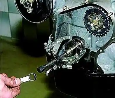
If the sprocket is tight, we press it off with a puller.
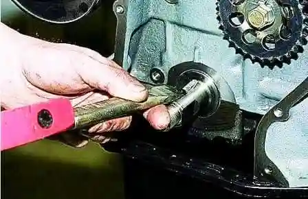
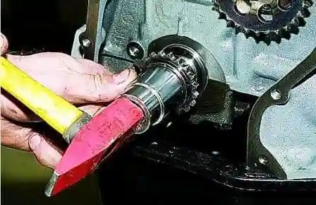
- With a punch, we drive the sprocket retaining key out of the groove.
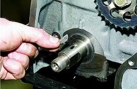
- We remove the key.
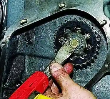
- We bend back the lock washer from the head of the bolt securing the oil pump drive sprocket.
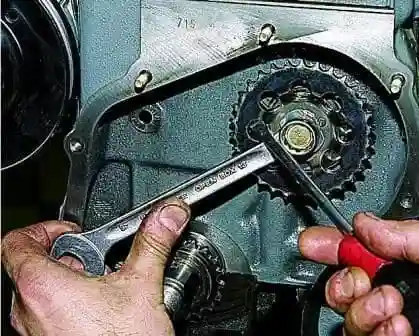
- Holding the sprocket from turning, we unscrew the sprocket securing bolt with a 17 mm socket.
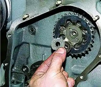
- We remove the bolt with the washers.
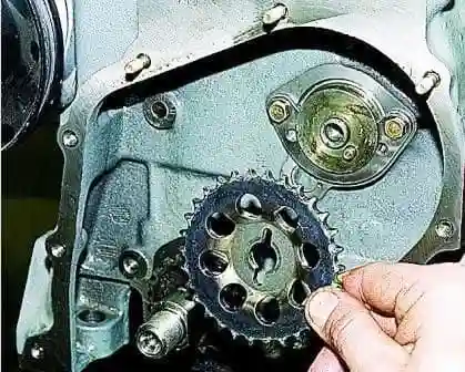
- We remove the sprocket from the shaft.
After inspection, we refit all the parts in the reverse order.
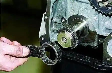
If the crankshaft sprocket is a tight fit, by tightening the pulley mounting nut we press it onto the crankshaft.
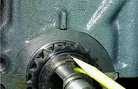
Before fitting the chain, we align the marks on the crankshaft and camshaft sprockets.
Inspection of the timing drive and oil pump chain
Wash the chain in paraffin and then check the condition of its links. Chips, cracks and other damage are not permitted on the rollers and plates. During engine operation, the chain components wear, so the chain stretches. It is considered serviceable as long as the tensioner maintains its tension, i.e. if the chain elongation does not exceed 4 mm.
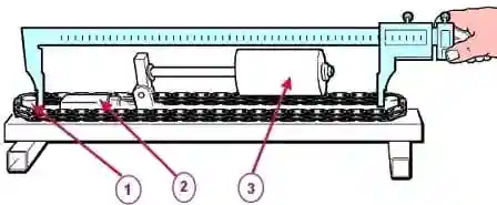
We determine the chain length using tool 67.7824.9521. The tool has two stepped measuring rollers 1, onto which the chain is placed when measuring its length. One of the rollers is fixed immovably in the tool body, and the second can move under the action of the measuring force P. With the help of counterweight 3 (see Figure 27), the chain is stretched with a force of 294 N (30 kgf) or 147 N (15 kgf). Adjusting nut 2 ensures the parallelism of the counterweight axis relative to the tool base.
The chain length is determined by the centre distance L of the measuring rollers 1 (see Figure 28). For a new chain, the length L is 495.4—495.8 mm. If, as a result of wear, the chain has a length of 499.8 mm, it should be replaced.

Measure the chain length in the following sequence:
- stretch the chain with a force of 294 N (30 kgf) by placing counterweight 3 (see Figure 27) in the extreme right position, then reduce the force to 147 N (15 kgf) by moving the counterweight to the extreme left position;
- repeat both operations once more;
- having measured with a vernier calliper the internal distance between the measuring rollers 1 and adding the roller diameter d to it, you obtain the chain length L (the distance between the axes of the measuring rollers).
Before fitting to the engine, lubricate the chain with engine oil.
The removal and inspection of the hydraulic chain tensioner are described in the article “Removal and inspection of the hydraulic chain tensioner”.


