
The timing chain tensioner is located on the right side of the engine above the coolant pump.
Oil is supplied to the hydraulic tensioner through a seamless steel tube with a diameter of 6 mm with tips.
The tube is connected to the threaded hole into which the fitting of the emergency oil pressure sensor is screwed.
Properly chosen bending stiffness of the tube made it possible to weaken its vibrations, besides, metal holders with rubber inserts are used to suppress vibration.
The tip of the tube is attached to the body of the tensioner using a fitting bolt, which is used to fasten the front brake hose of rear-wheel drive vehicles and all-wheel drive VAZ families.
The tensioner plunger presses on the shoe, which, like the chain guide, is made of wear-resistant plastic.
The tensioner shoe pivots on an axle located at the bottom of the cylinder block, to the right of the crankshaft sprocket.
Removing the chain tensioner

Using a 13 head, unscrew the bolt securing the oil supply pipe to the tensioner

Remove the copper washer and take out the bolt fitting with the copper gasket

Using a 10 head, we evenly unscrew the two nuts securing the tensioner to the head of the block

Removing the tensioner
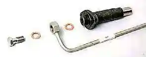
Details of fastening the oil supply pipe to the tensioner

A gasket is installed under the tensioner
After inspection and fault detection, install the tensioner in reverse order
Operation and fault detection of the hydraulic chain tensioner
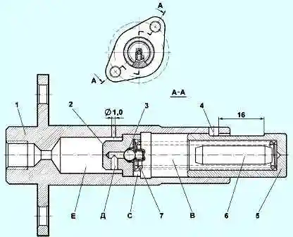
Oil from the lubrication system through tube 3 (see Fig. 7) enters the cavity (E) of the tensioner, then through the hole (d) and valve assembly 2 enters the working cavity (B) and presses on plunger 5.
The body 1 of the tensioner has a hole with a diameter of 1 mm to bleed air from the cavity (E).
The diametral gap between body 1 and plunger 2 should be 0.018-0.024 mm and is measured as the difference between the maximum measured diameter of plunger 2 and the minimum measured diameter of body 1.
When repairing, the tensioner body and the plunger form a pair, in which the replacement of one part with another after the gap is selected is not allowed.
Plunger 2 must move without sticking in body 1 by a stroke equal to 16 mm.
When installing on the engine, the tensioner must be free of oil, pin 4 must not protrude from the housing.

")
")
")
")
")
")
")
")